Handling Parts In A Robotic Cell
Here’s a review of the workholding and workhandling challenges a shop faces as it moves a part through a robotic cell, from serving up the blanks to the transfer of the final workpiece to post processing and gaging. Productivity, Inc. takes the reader through a few of their cells that they've installed using Fanuc robots and a variety of other machine tool equipment.
When a shop implements a robotic cell in its CNC machining operations, the goal is clear: Save money through better spindle utilization, more efficient use of labor and more consistent production. In fact, robotic machine tending can lower a company’s labor cost on a single machine by more than 90 percent. But it takes some careful planning to make a system work effectively in any given production environment, and determining how the workpiece will move throughout the robotic cell is a major component of the process.
Robotic integrators such as Productivity Inc. (Minneapolis, Minnesota) provide a valuable service, acting as an effective supplier for the necessary planning and implementation process. Founded in 1968, Productivity, whose core business is the sale of CNC machine tools, has been helping customers with the automation of precision machining processes using Fanuc robots. Experiencing steady growth, the company is currently adding more than 20,000 square feet of additional space, enhancing the ability to apply
robotics.
Don Engles, manager of Productivity’s automation group, says, “When people consider purchasing a robotic cell, of course they think about the robot, but other important things that are often overlooked are grippers, guarding, door openers, workholding, part in-feed and out-feed devices, vision systems, and the total integration of the mechanical and electrical components.” He adds that a significant part of planning a cell is determining the configuration requirements for the workpieces that must be run. “Robotic systems that are simple generally tend to be more versatile, easy to bring new parts into, and ultimately have higher uptime.” As complexity increases, so does change-over time. Changes to the part mix also become more difficult.
Moving The Workpiece
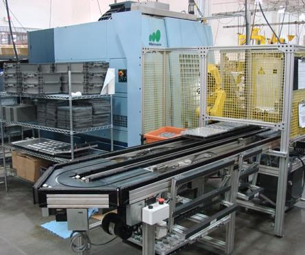
Various methods of part handling can be used to move the part through the entire robotic cell. The first step is getting the material to the operation. Sometimes a bar feeder can provide the spindle with continuous material, but often conveyor systems, nested pallets, vertical stacking or drawer units are required to bring blanks, forgings or castings into the operation. Don explains, “Productivity often uses conveyors and Fanuc’s robust ‘iRVision’ 2D vision system to guide the robot to a single layer of randomly spaced parts.”
Once the workpiece is accessible to the robot, the robot must know where to find it and be able to pick it up. In simpler cells, accurate placement on the conveyor or in the pallet (and proper programming of the robot) is the key for the robot to find the workpiece. Advanced vision systems allow more complex part location for bin picking, but this process presents other issues when trying to get parts out of corners of the bin or when unexpected items are dropped in the mix of parts.
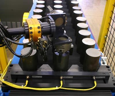
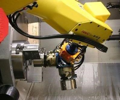
The “end-of-arm” tool assembly is a significant part of the cell design. Productivity tries to use commercially available components, but custom designs are very common. Often, it is possible to simply change fingers to compensate for these custom needs. Fixtures can also be used to compensate for varying part designs. These fixtures provide a common tooling point, eliminating the need to design specific fingers for each part design. Sometimes, finger sensors are used to signal whether the fingers are open or closed to provide a definite indication that a part is in the grippers.
As the blank is delivered to the machine, the previous workpiece must be removed. Therefore, a second gripper head is common to allow the exchange in one operation. Often a blowoff mechanism is also used to clean the fixture before placing the next blank. Clearance for necessary end-of-arm tooling, along with the potential for multiple workpieces in the work area, must be considered.
According to Don, the single most important consideration of automation is controlling the chips that are made in the process. “You don’t want to have long strings that come up and get all over things,” he explains. “Before even implementing the automation, we make sure the process is refined to control the chips through speeds, feeds and chipbreakers.”
When the finished part comes out, it is placed on the out-feed mechanism—typically a conveyor. Parts are often palletized upon exiting as well. These parts then can be transported to any number of operations, from cleaning to inspection to packaging. Many of these operations can be automated as well, depending on the features included in the cell itself.
A Solid Example
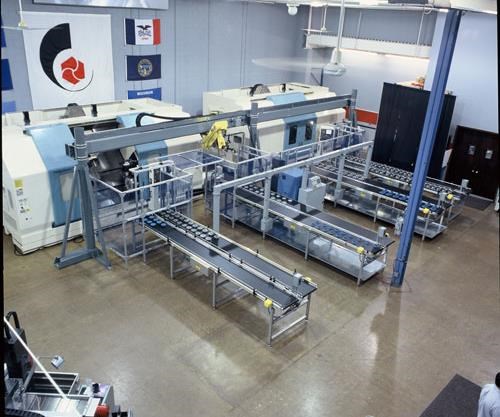
Productivity works closely with Wanner Engineering (Minneapolis, Minnesota), using the company’s high-pressure pumps for its own high-pressure coolant systems. Wanner Engineering builds pumps capable of as much as 2,500 psi. Productivity installed a robotic cell at Wanner that includes a Fanuc M16iB six-axis robot and a Nakamura-Tome WT-150 CNC dual-spindle lathe with live tooling (see the Learn More at the end of this article for a link to video of the cell). The cell uses a conveyor rather than a palletized in-feed, but it has a flexible escapement system. Don says, “Our company installs more conveyors than any other systems. People like them because they are simple. If a vision system is required, we just add a light beam across the conveyor as an end stop. The conveyor brings the part into the camera’s field of view, an image is taken and the robot is guided to pick up the part.”
Although about 90 percent of the systems Productivity installs have vision systems on them, Wanner’s does not. It is a fairly basic system. Lot sizes are in the 100s, with about 60 different part numbers that the company runs across the cell. Although the number of change-overs is high, they take only about 15 minutes each.
One example of a family of parts run in this cell is a motion cam (for inside the high-pressure pumps) that varies in size, angle and offset, depending on its corresponding pump size and flow. Made from 12L14 steel, about 2,500 of each of the 11 parts in the family are made each year. Before going to the cell, blanks ranging from 2 to 19.5 pounds are sawed from 12-foot barstock.
The saw-cut blanks are loaded three-wide through alignment dividers, which provide proper spacing between the blanks for the robot to locate them and pick them up. Placement in the forward/backward direction is not critical, requiring only enough space from one to the next to allow the robot arm to come down and grip the part. At the end of the in-feed conveyor are three proximity switches, in the center of each lane, that turn on when a blank part approaches. As soon as one of these switches is satisfied, the in-feed stops and the robot is signaled that a blank is in position at that location, ready to be loaded. As that part is lifted out, the conveyor moves forward again until another switch is satisfied. As the robot empties the in-feed conveyor, the operator must restock it.
Most of the parts in this family are finished complete in one operation. The biggest sizes in the family are exceptions because they are too long to allow the robot to handle both the blank and the finished part inside the machine at the same time. After the 5-minute cutting cycle, the robot is waiting to load the next blank. The servodriven door opener is activated and the robot places the new blank in the main spindle, removes the finished part from the subspindle and places that part on the out-feed conveyor.
Customized grippers for part handling are not required for this family of parts. In some cases, fragile, thin-walled brass or aluminum parts may need to be handled differently. Todd Bellin, manager of machining operations at Wanner, says the standard grippers on the robot are fine for these operations. “Sometimes we do parts that cannot have gripper marks. The finish is not critical for these parts, though. We still want attractive parts, but these will go inside a pump, never to be seen again.”
The robot places the finished parts on the out-feed conveyor, keeping track of where to place the parts with a numbering scheme (in position one, two or three). Once three are placed across, the out-feed conveyor moves to its next position. At the end of the conveyor, the operator must remove the parts manually. The bigger parts that require the second operation are eventually loaded back onto the in-feed and the next program is initiated. Finished parts are transported to the assembly area for installation into the pumps.
Lending A Hand
Although the example provided by Wanner Engineering is relatively simple, it demonstrates an overview of the strategic thinking that goes into planning a robotic cell and how a part is handled all the way across the operation. More specifically, at the heart of the cell, the robot must be able to handle the workpiece precisely. Depending on the shape of the part, two-jaw, three-jaw or custom grippers may be used. Although different types of jaws are available, whether vacuum grippers, jaw sets or electromagnets, Don explains that the pneumatic grippers that are greased for life tend to be the most reliable. “They’re good for millions of cycles and need very little attention. Vacuum grippers tend to get covered with debris because they inhale chips and other materials and get less effective over time. Magnetic grippers sometimes pick up other unwanted materials that affect precision in the machine’s workholding device.”
But no matter how much effort is given to automating the process, human intervention is always necessary at some point. An operator once performed the robot’s functions. Someone was there at all times to load and unload the part, and it was difficult to maintain a real steady output. Now the operator is still responsible for loading and unloading the pallets and other supervisory functions. The components of the cell never take a break, but they won’t run themselves indefinitely, either. A human must be around to keep track of part quality, tool changes and unexpected issues. The increased consistency of output is a welcomed reward, but the operator’s contributions cannot be overlooked.
Related Content
Automation in the Alps: Studer AG Unveils New Grinding Concepts
Studer AG, member company of United Grinding, held its annual press conference at its Swiss Alps location earlier this month to announce its new automatic loaders to accompany its existing grinding machines as well as other offerings and automation features.
Read MoreInside the Premium Machine Shop Making Fasteners
AMPG can’t help but take risks — its management doesn’t know how to run machines. But these risks have enabled it to become a runaway success in its market.
Read MoreReinventing the Wheel with Robot-Automated CNC Multitasking
One race team discovers how to efficiently manufacture a new wheel nut design for the next-generation NASCAR stock car with the help of a CNC mill/turn and a built-in robot.
Read MoreStarting Small with Automation
Quick-change workholding and flexible robotic automation started this small shop on the path to success.
Read MoreRead Next
Seeing Automated Workpiece Measurement in Real Time
User-friendly inspection software for CNC machining centers was shown at IMTS 2024 monitoring measurements between and after machining while performing SPC based on recorded measurement values.
Read MoreDo You Have Single Points of Failure?
Plans need to be in place before a catastrophic event occurs.
Read MoreA Tooling Workshop Worth a Visit
Marubeni Citizen-Cincom’s tooling and accessory workshop offers a chance to learn more about ancillary devices that can boost machining efficiency and capability.
Read More


