Tools and Technologies for Deep Hole Drilling
Understanding the challenges of deep hole drilling and knowing how to select and apply the appropriate tools will help a shop profit from this operation.
Effective, efficient production of deep holes can present a number of challenges. To produce a quality final product while keeping costs under control, shops must be able to achieve accuracy, repeatability and sufficient surface finish while maintaining predictable tool life. Choosing the best tool for the job and implementing the right operating procedures can help make this difficult operation productive and profitable.
At a recent event at Big Kaiser Precision Tooling Inc., Cory Cetkovic, Sphinx product manager, presented his tips for making the most of deep hole drilling operations. This article breaks down his key points.
Common Challenges
Tool runout control. One of the most significant challenges of deep hole drilling is maintaining control of runout, which increases with cutting tool length. Replacing a cutting tool that is 6× diameter in length with one that is 30× diameter, for instance, will result in substantially larger runout. A more accurate method of toolholding, or perhaps a more accurate machine tool, can help to compensate for the increasing runout from longer tools.

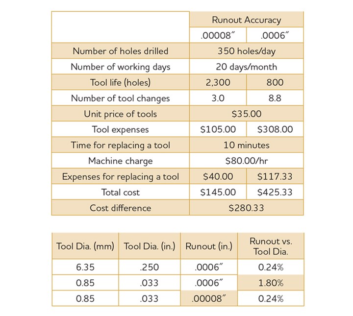
Fig. 1. Total indicated runout increases with cutting tool length. Maintaining an adequate level of accuracy maximizes cutting tool performance and tool life.
Runout influences tool life. One example (Figure 1) demonstrates the importance of accuracy, even without the use of a deep hole drill. It shows that 2.9 times longer tool life can be attained with runout of 0.00008 inch versus 0.0006 inch of runout. Using a 1/4-inch drill with 6 tenths of runout, the runout versus the tool diameter is roughly a quarter of a percent. With an ER 32 collet chuck, replacing the existing collet for the 1/4-inch drill with a collet for a 0.85-mm drill allows the system to maintain roughly the same level of accuracy—1.8 percent of the drill’s diameter. The indication is that a much heavier load is being placed on the small cutting tool by using the same quality toolholder that was used for the larger drill. To maintain the same level of accuracy for the 0.85-mm drill, 80 millionths of runout is required. So when using small, longer drills, an accurate toolholder on an accurate piece of equipment is important. These effects are amplified further when using longer tools and are more prevalent with micro cutting tools.
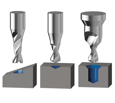
Drill walking. A common issue when using longer deep hole drills (particularly those in excess of 12× diameter) is the drill “walking” across the part. When attempting to enter the part, because the drill is rotating, it will want to move across the surface of the part rather than drilling downward into it. A clean, perpendicular surface is important to help prevent this issue. A cast or rough surface may be manageable with shorter, stubbier (more rigid) drills, but a longer drill will have a higher tendency to walk, which quickly leads to tool breakage. A dull cutting edge also promotes the tendency to walk, so knowing when to resharpen or replace the drill is important.

The longer the drill, the more tendency it will have to walk. Other circumstances such as rough surfaces, dull cutting edge or inclined surfaces can also increase the likelihood of walking.
A center drill can be used to improve the accuracy of the drill that follows. A center drill creates a point angle that is larger than the point angle of the deep hole drill, with the intention of guiding the deep hole drill into the centerline location. Pilot drilling serves a similar purpose to center drilling except it provides a bit more guidance to the deep hole drill by having the pilot hole drilled to a depth that is 1× to 2× the diameter. When drilling on an incline surface, the drill is likely to walk down the incline. Milling a flat on the surface, and even spot or pilot drilling into the flat can prevent walking.
The above procedures reduce the probability of breaking the drill’s primary cutting edge or even chipping a corner on entry. Often, when a corner is chipped, several bad parts may be made before it is noticed. Following these procedures will reduce the chances of failed parts and will create a more consistent and reliable process in the long run.
Chip Control. Most deep hole drills use internal coolant to assist with chip evacuation. Often, however, internal coolant is not available. The tool’s diameter may be too small to accommodate internal coolant, such as the case with micro deep hole drills—below 1.5-mm diameter and as long as 80× diameter in length. Application requirements may also prohibit the use of coolant because of material makeup. Also, the machine tool, particularly in the case of older equipment, may not have internal coolant capabilities.
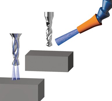
The advantage of using internal coolant is that it improves chip evacuation while cooling the cutting edge. Coolant is flushed down to the bottom of the hole, which, in turn, is pushing the chips back up toward the top.

Most deep hole drills use internal coolant to assist with chip evacuation while cooling the cutting edge. However, certain strategies can be used to improve performance in applications where external coolant must be used.
Without internal coolant, a pecking cycle can be used to pull the chips out of the hole. Usually when a pecking cycle is used with external coolant, it is in the range of 1× to 2× diameter in length, and more often than not, the tool is retracted almost all the way out of the top of the hole, leaving only the tip engaged. This process requires a substantial amount of time relative to the use of internal coolant.
Tool coatings can also play a significant role in chip control. New coatings are available every year, and many of these modern coatings perform better at higher speeds. The key is to use a coating that is suitable for the workpiece material and to operate at speeds recommended for that coating. Not running the appropriate speeds may result in edge buildup that leads to poor chip control and tool failure.
Hole Straightness
The “margin” is the portion of the drill that is actually contacting the hole. A two-margin drill, commonly referred to as a single-margin drill (because it has one margin per flute) is preferred in long chipping materials. The lower number of margins provides additional clearance in the longer chipping materials, allowing the tool to drill that hole in a situation that may not have been possible using a four-margin drill (commonly referred to as a double margin drill).
Another way to improve hole straightness is to use a series of drills, beginning with a shorter, more rigid one and moving to progressively longer ones.
A four-margin drill provides excellent hole straightness compared with a two-margin drill. The disadvantage is that it has a tendency to break in longer chipping materials. Although not as common, six-margin drills are also available. The additional contact point helps generate an even straighter hole while maintaining a more accurate diameter. So more margins add accuracy while maintaining a higher surface finish, but restrict the amount of clearance for chip evacuation.
Another way to improve hole straightness is to use a series of drills, beginning with a shorter, more rigid one and moving to progressively longer ones. If an 80× diameter in length drill is used to create an 80× diameter hole, it has a good probability of walking across the surface of the part. It also my not produce good quality straightness simply because it is so long and flexible. One way to avoid that issue is to drill a pilot hole 2× diameter, then drill a 20× diameter, then drill the 80× diameter. Guiding the 80× diameter drill through the 20× diameter hole should provide an adequate amount of straightness.
Caution should be taken in selecting the series of drills. The previous drill in the sequence should have a larger point angle and a slightly larger diameter to avoid any interference. For instance, from the 20× to the 80× diameter, the tolerances on the drill diameter will go from positive on the 20× diameter to negative on the 80× diameter. A 1-mm 20× drill might have anywhere from a 1-mm to a 1.004-mm diameter. The 80× diameter drill, then, would have the same tolerance, but on the negative side. The 20× diameter drill should also have a larger point angle.
Drill Selection Guidelines
Beyond being aware of the diameter and the point angle of the drill with respect to the pilot tool or spotting tool, it is also important to avoid the use of deep hole drills with unused length. The unused length accumulates runout, it is added expense, and it decreases the level of rigidity of the overall setup.
The other key to drill selection relates to whether or not internal coolant will be used and if it will be high pressure. Typically, cycle time is reduced when using drills with internal coolant. Internal coolant is available from various manufacturers for diameters as small as 0.50 mm.

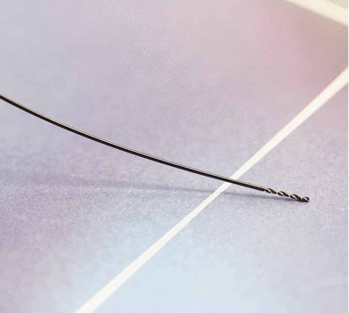
New technology is available for external coolant that allows manufacturers to use a grain structure to create cutting tools that have a surprising level of flexibility.
New technology is available for external coolant that allows manufacturers to use a grain structure to create cutting tools that have a surprising level of flexibility. Some new coating technologies are also recently available. Typically, tools as small as 0.2 mm can be coated, but the highlight of this new coating is that once the tool is ground and coated, no post-process polishing is required. The coating particles are so fine that they fill the porous carbide, creating a smooth surface finish.
Operating Procedures
For external coolant, the process should begin with a pilot hole from 1× to 2× diameter in length, followed by entry of the deep hole drill at roughly 500 rpm and 25 to 50 percent of the maximum feed rate. The slower feed rate and rpm reduces the risk of damaging the drill’s cutting edge. Once into the pilot hole, drilling can proceed at 100 percent of the feed and speed until reaching the end of that pecking cycle. At that point the drill is retracted, pulling the chips out of the hole but leaving the tip engaged to retain location. Once the chips are cleared, the pecking cycle begins again until reaching the bottom. The drill is then retracted at 100 percent of the speed and 200 to 500 percent of the feed rate. (Once the hole is complete, it is important that the drill remains rotating.)
This process may seem long, but the purpose is to create a consistent environment where tools have a predictable tool life. Many shops may be pleased to achieve a range of 2,000 to 4,000 holes per drill, but more consistency reduces scrap rate significantly, and this procedure will provide it.
The deep hole drilling operating procedure for internal coolant is similar. It should begin with a pilot drill. With the coolant off, the deep hole drill should enter the pilot hole at about 500 rpm and anywhere from 200 to 300 percent of the operating feed rate. Turning the coolant on prematurely, (before the drill is inside the hole) will cause the drill to whip around, and it likely will not enter the pilot hole cleanly, causing it to break. Once the drill is inside the pilot hole, the coolant is turned on and the drill should run at 100 percent of the speed and feed. After reaching the bottom of the hole, the drill should be retracted at the maximum feed rate, rotating at roughly 500 rpm. The coolant should be turned off before the drill is outside of the hole.
Following these steps for deep hole drilling with external or internal coolant will provide consistent, predictable performance that will allow reliable tool life forecasting. The goal is to maintain control of the drill, protecting the cutting edges from damage and premature wear. Deep hole drilling can be one of the more challenging metalworking operations, but when proper procedures are in place, it can be handled with few issues.
Related Content
The Ins and Outs of Inserts
Understanding how inserts are made provides valuable insight into how their performance can be optimized.
Read MoreWhat Is Trochoidal Turning? How Might Shops Benefit From It?
While trochoidal milling might be a more well-known toolpath strategy, trochoidal turning can offer similar benefits such as high material removal rates especially for rough-turning operations.
Read MoreThe Value of Swiss-Types Milling Rectangular Medical Parts
High-speed spindle technology was key to effective milling of small cardiac monitoring components complete on a CNC sliding-headstock machine platform instead of running them across two mills.
Read MoreBroaching Tool Technology For Lathes Used to Slot Inconel Parts
This shop finds value in using an indexable-insert-style broaching tool to create blind-hole slots in heat-treated Inconel aerospace parts on a CNC lathe.
Read MoreRead Next
Tips for Improved Holemaking
A few drill types dominate holemaking, a machining process made up of sub-areas that are evolving along with changing drill capabilities.
Read MoreMicro-Drilling: 9 Questions to Answer Before Beginning
Applications for micromachining continue to grow. Successful machining with small tools calls for a different set of process skills on the shop floor.
Read More5 Aspects of PMTS I Appreciate
The three-day edition of the 2025 Precision Machining Technology Show kicks off at the start of April. I’ll be there, and here are some reasons why.
Read More


.jpg;maxWidth=300;quality=90)


