Linear Motor Basics
A steady increase in practical industrial applications has secured a place for linear motors. Here's an overview of the various types of linear motors and what differentiates them from their rotary counterparts.
Share
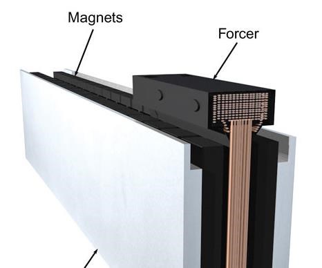
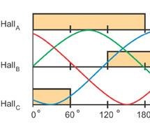
The linear motor has really come of age in the past decade through a dramatic increase in practical and beneficial industrial applications. The linear motor is often described simply as a rotary motor that has been rolled out flat, and the principles of operation are the same. The forcer (rotor) is made up of coils of wires encapsulated in epoxy, and the track is constructed by placing magnets (usually high power “rare earth” magnets) on steel. The forcer of the motor contains the windings, Hall-effect board, thermistor (to monitor temperature) and the electrical connections. In rotary motors, the rotor and stator require rotary bearings to support the rotor and maintain the air gap between the moving parts. In the same way, linear motors require linear guide rails to maintain the position of the forcer in the magnetic field of the magnet track. Just as rotary servomotors have encoders mounted to them to give positional feedback of the shaft, linear motors require positional feedback in the linear direction. By using a linear encoder, position is directly measured at the load for increased accuracy of the load position.
The control for linear motors is identical to rotary motors. Like a brushless rotary motor, the forcer and track have no mechanical connection (no brushes). Unlike rotary motors, where the rotor spins and the stator is held fixed, a linear motor system can have either the forcer or the magnet track move (most positioning system applications use a moving forcer and static track). With a moving forcer motor, the forcer weight is small compared with load. However, a cable management system with high-flex cable is required. With a moving track arrangement, the motor must move the load plus the mass of the magnet track, but no cable management system is required.
Similar electromechanical principles apply whether the motor is rotary or linear. The same electromagnetic force that creates torque in a rotary motor creates a force in its linear counterpart. Hence, the linear motor uses the same controls and programmable positioning as a rotary motor.
A linear motor can be flat, U-channel or tubular in shape. The configuration that is most appropriate for a particular application depends on the specifications and operating environment.
Cylindrical Moving-Magnet Linear Motors
In the cylindrical moving-magnet design, the forcer is cylindrical in construction and moves along a cylindrical bar that houses the magnets. These motors were among the first to find commercial applications but do not exploit all of the space-saving characteristics of their flat and U-channel counterparts. The magnetic circuit of the cylindrical moving-magnet linear motor is similar to that of a moving-magnet actuator. The difference is that the coils are replicated to increase the stroke. The coil winding typically consists of three phases, with brushless commutation using Hall-effect devices. The forcer is cylindrical and moves up and down the magnetic rod. This rod is not suitable for applications sensitive to magnetic flux leakage, and care must be taken to ensure that fingers do not get trapped between the magnetic rod and an attracted surface.
One potential problem with the design of tubular motors manifests when the length of travel increases. Because the motor is completely cylindrical and travels up and down the rod, the only point of support for this design is at the ends. The length will always have a limit before the deflection in the rod causes the magnets to contact the forcer.
U-Channel Linear Motors
U-channel linear motors have two parallel magnet tracks facing each other with the forcer between the plates. The forcer is supported in the magnet track by a bearing system. The forcers are ironless, which means that there is no attractive force and no disturbance forces generated between the forcer and magnet track. The ironless coil assembly has low mass, allowing for very high acceleration.
Typically, the coil winding is three-phase, with brushless commutation. Increased performance can be achieved by adding air-cooling to the motor, and there are even water-cooled versions available. This design is better suited to reduce magnetic flux leakage because the magnets face each other, housed in a U-shaped channel. The design also minimizes the risk of injury from the powerful magnetic attraction.
The design of the magnet tracks allows them to be combined to increase the length of travel, with the only limit to operating length being the length of the cable management system; encoder length available; and the ability to machine large, flat structures.
Flat Linear Motors
There are three types of flat linear motors (all brushless): slotless ironless, slotless iron and slotted iron. Choosing between these types of motors requires an understanding of the application.
Slotless Ironless: The slotless ironless flat motor is a series of coils mounted to an aluminum base. Because of the lack of iron in the forcer, the motor has no attractive force or cogging (the same as U-channel motors). This design helps with bearing life in certain applications. Forcers can be mounted from the top or sides to suit most applications. This type of motor is ideal for smooth velocity control, such as scanning applications, but yields the lowest force output of the flat track designs. Generally, flat magnet tracks have high magnetic flux leakage, so care should be taken while handling these to prevent injury from magnets trapping the operator between them and other attracted materials.
Slotless Iron: The slotless iron flat motor is similar in construction to the slotless ironless motor, except the coils are mounted to iron laminations and then to the aluminum base. Iron laminations are used to direct the magnet field and increase the force. An attractive force is created between the forcer and the track that is proportional to the force produced by the motor. As a result of the laminations, a cogging force is also present. Care must be taken when presenting the forcer to the magnet track as they will attract each other and may cause injury. This design produces more force than the ironless design.
Slotted Iron: In this type of linear motor, the coil windings are inserted into a steel structure to create the coil assembly. The iron core significantly increases the motor’s force output by focusing the magnetic field created by the winding. A strong attractive force between the iron-core armature and the magnet track can be used advantageously as a preload for an air bearing system. These forces, however, can cause increased bearing wear. Skewing the magnets can reduce cogging forces.
Here To Stay
Before the advent of practical and affordable linear motors, all linear movement had to be created from rotary machines by using ball or roller screws or belts and pulleys. For many applications (for example, where high loads are encountered and where the driven axis is in the vertical plane), these methods remain the best solution. However, linear motors can offer many distinct advantages over mechanical systems such as very high and very low speeds, high acceleration, almost zero maintenance (there are no contacting parts), and high accuracy without backlash. Achieving linear motion with a motor that needs no gears, couplings or pulleys makes sense for many applications where unnecessary components that diminish performance and reduce the life of a machine can be removed.
Read more:
Linear Motors: Practical for Your Shop?
Related Content
Tips for Troubleshooting and Repairing Chip Conveyors
A nonfunctioning chip conveyor can cause a high-production machine to be down for an extended period of time. Here is some troubleshooting advice if you’re having issues with your chip conveyors.
Read MoreVideo: Why a Production Machine Shop Started a Baseball Bat Company
A 153-year-old manufacturer of precision, metal pins recently started a side business creating custom wooden baseball bats. The reasoning behind establishing this new company is intriguing, as is how it has helped create a stronger bond with the local community.
Read MoreCraftsman Cribsheet No. 128: Why Do Machinists Say Tenths Instead of Ten Thousandths?
In machinist parlance, a tenth is a tenth of a thousandth, not a tenth of an inch.
Read MoreUnderstanding Micro-Milling Machine Technology
Micro-milling can be a companion process to turning-based production machining. This article looks at some of the technologies that go into a micro-milling machine and why they are important to successful operation.
Read MoreRead Next
Seeing Automated Workpiece Measurement in Real Time
User-friendly inspection software for CNC machining centers was shown at IMTS 2024 monitoring measurements between and after machining while performing SPC based on recorded measurement values.
Read More






.jpg;maxWidth=300;quality=90)

