Tighter Requirements Call for Optimized Deburring Processes
Burrs and chips are unavoidable in virtually all high production manufacturing processes. Today, the removal of these remnants from the production process is an absolute must for high quality, precision parts.
Burrs and chips are unavoidable in virtually all high production manufacturing processes. Today, the removal of these remnants from the production process is an absolute must for high quality, precision parts. Strict requirements for deburring quality and process reliability must be fulfilled while continuing to increase the efficiency of the deburring process.
Whether parts are manufactured by machining, metal forming or master forming, deburring usually doesn’t fall into one of the part manufacturer’s areas of core competence. Therefore, the removal of these remnants from the production process is often still seen as a necessary evil that increases unit costs. However, because of ever stricter requirements for product quality and functionality, intermediate and downstream processes such as deburring are becoming more and more significant across all industry sectors. Meanwhile, component geometry is getting continuously more complex, and parts are being made of new materials and material combinations. To achieve sufficient product quality and economic efficiency, technologies must be ideally matched to varying deburring requirements for good process reliability.
Predicting and Minimizing Burrs
Machined workpieces often include difficult to access areas that must be deburred, such as undercuts, grooves, slots, internal holes and holes that cross through each other. The more complex the workpiece is, the more difficult it is to get at the burrs. It’s still crucial to remove burrs reliably, in accordance with the specified requirements and without adversely affecting the material. A further challenge is presented by so-called secondary burrs, which are caused by the deburring tool during the deburring process.
A model used to predict and minimize burrs makes a significant contribution to reliable and efficient deburring of workpieces made of steel and nonferrous metals. It was developed by Dr.Beier-Entgrattechnik on the basis of a metal forming approach for the formation of burrs as a practical application. The goal is to provide production planning and design engineering with a tool based on a quick and practical means for predicting the formation of burrs to optimize processes and make them more efficient. The model incorporates findings from materials science and an engineering viewpoint of the machining and forming processes. The formation of burrs depends primarily on the material’s stress-strain behavior and the prevailing cutting forces. Elastic and plastic material characteristics are derived from the results of tensile tests. The determination or specification of cutting forces is based on relationships prevailing in the field of machining technology.
Using the Right Tool
In the case of machined workpieces that are produced in large numbers, deburring takes place at the end of the automated manufacturing process, or after a sub-process. From an economic standpoint, a fully automated, high-speed deburring process that is executed directly in the machine tool is the ideal solution. Reliable, automated and highly effective deburring methods are required to prevent any slowdown of manufacturing processes with short cycle times and to ensure uniform quality. The tools that are used must also be matched to the application and must ensure that deburring results meet the specified requirements, even for complex workpieces with difficult to access burrs. Furthermore, no secondary burrs may be caused by the deburring process.
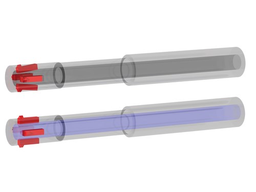
Special HSD (high-speed deburring) tools have been developed for applications of this nature. The cutting force required by these tools is not generated by spring elements, but rather by a pressure medium such as coolant, oil, compressed air or minimum lubrication lines that are already available. This system has the advantage of maintaining force applied to the cutter at a constant level over a range of cutting tool deflection. The cutters are pressed in the furthest inside a drill hole by its walls. Because no burrs are here, excessive force applied to the cutter would alter or even damage the surface and would result in unnecessary wear. HSD tools develop the most force when the cutters are open very wide, such as at the edges of drill holes where the drill first enters or exits the material, or the edge of a cross-hole or a groove which needs to be deburred. This is precisely where force is required for deburring, and if necessary, for the production of a chamfer. These tools permit forward and reverse deburring, as well as the deburring of cross-holes, without design changes.
All cross-holes, as well as the main hole’s point of entry and exit, can be deburred through the main hole with an HSD tool in a single work step. Different diameters of the cross-holes and any grooves or oblong holes that need to be deburred don’t play any role in this respect. At the same time, specially shaped cutters ensure that the burrs aren’t only bent over or pressed into the cross-holes.
Burr-Free Crossing Holes
The automated CBD (cross bore deburring) process developed by Heule Werkzeug AG in Switzerland, a further development of the modular COFA tool system, is still being tested. In this new generation, the cutter and the cutter retainer are separate. The COFA system is designed for increased economic efficiency, as well as improved productivity, and is opening up a larger range of applications as well. Integrating the tool into the machine tool makes it possible to produce already deburred workpieces. No pre-adjustment of the COFA tool is required—the mechanically guided deburring cutter can be inserted or replaced manually, or with a jig. It ensures uniform, radius-shaped deburring without any secondary burrs with a defined cutter at even and uneven drill-hole edges. Forward and reverse processing is completed in a single work step without reversing the spindle’s direction of rotation, and without time-consuming turning of the workpiece. Part tolerances are compensated for automatically by the tool’s operating principle. The COFA tool can also be used for workpieces made of difficult to machine materials such as stainless steel, titanium and Inconel.
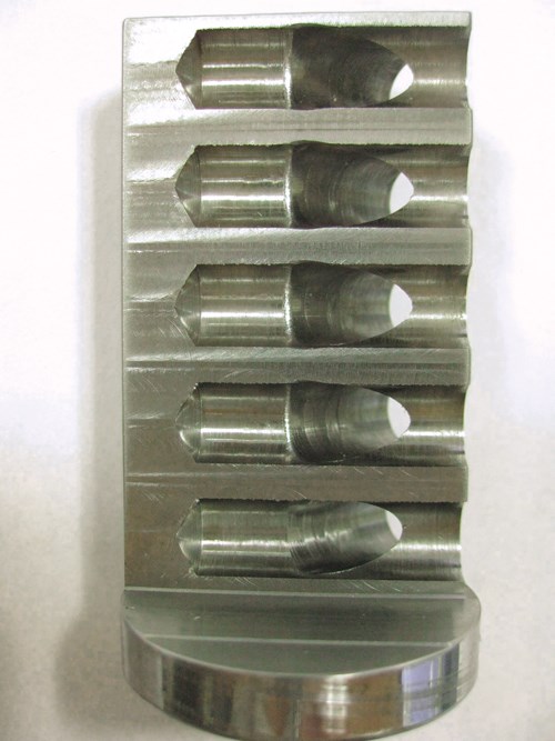
Use of the COFA system is limited, however, in cases where holes cross through each other and have diameter ratios approaching 1-to-1 with an intersection angle of less than 90 degrees. Heule has developed the CBD process for applications of this sort, such as in the removal of internal burrs at the back of oil holes. This tool system is also of modular design and can be integrated into the machine. It makes use of a modified operating principle: Deburring is axial (comparable with broaching) and feed is radial. As a result, the CBD process makes it possible to deburr cross-holes with almost any diameter ratio and with intersection angles of significantly less than 90 degrees in an automated fashion within the machining process with a defined cutter.
Read Next
A Tooling Workshop Worth a Visit
Marubeni Citizen-Cincom’s tooling and accessory workshop offers a chance to learn more about ancillary devices that can boost machining efficiency and capability.
Read MoreDo You Have Single Points of Failure?
Plans need to be in place before a catastrophic event occurs.
Read More5 Aspects of PMTS I Appreciate
The three-day edition of the 2025 Precision Machining Technology Show kicks off at the start of April. I’ll be there, and here are some reasons why.
Read More


.jpg;maxWidth=300;quality=90)


