Two New Twists on Thread Whirling
Thread whirling as a metalworking process dates to the 1940s. Recently, developments in production speeds, based on this increasingly popular process, are impacting thread manufacturers.
Few thread production processes are as efficient as thread whirling. Although not a new process, its popularity has grown as a primary process choice with the development of thread whirling tooling for single-spindle Swiss-type machines becoming more readily available.
Thread whirling on general-purpose machines such as CNC Swiss-types provides an inexpensive alternative to investing in dedicated thread whirling machine tools. When it comes to producing OD threads in difficult-to-machine materials such as Inconel, titanium and stainless steels, few processes can compete with thread whirling.
In the thread whirling process, the blank to be threaded extends from the machine spindle, or through a guide bushing, and is rotated at low rpm. A ring-shaped toolholder, mounted on a whirling attachment, contains indexable insert cutters, evenly spaced around the periphery of the ring.
The attachment is canted to create the pitch of the thread to be produced as the blank is fed through the cutter. The attachment and spindle are rotated in the same direction, but the attachment rotates at a much higher speed than the spindle. As the cutting tool “whirls” or orbits about the blank, each of the inserts, in turn, takes a bite out of it. The inserts then impart the thread’s specified geometry to the blank.
Sliding headstock machines take advantage of the Z-axis feed capabilities of the machine to allow radial cutting feeds without deflection because the cutters are close coupled to the guide bushing. Thread whirling attacks the workpiece axially with the tool rotating around the blank as it is fed in the Z axis. Because of the cutting force’s direction, deflection from thread whirling is reduced.
By dividing the cutting load among the number of inserts located on the toolholder’s periphery, tool life is significantly improved compared with single-point turning. It also allows for higher feeds, which results in shorter cycle times.
However, little or nothing stands still in metalworking and thread whirling is no exception. Recent developments in insert geometry creation and arrangement of those inserts on the cutting toolholders is helping shops take advantage of the traditional advantages of thread whirling coupled with significant performance improvements in tool life and cycle times.
Enter ‘Turbowhirling’
Earlier this year I attended a biennial Technology Days event at the Tübingen, Germany, headquarters of cutting tool manufacturer, Paul Horn GmbH. The company has a manufacturing facility in Franklin, Tennessee, which is impressive and growing, but it’s hard to beat visiting a company’s headquarters.
Technology Days is open to Horn’s customers, distributors and members of the press. I look forward to these visits because each time I have participated, I have come away with generic technical information that can be used in PM. This year was no exception.
One of the eight technical presentations, all in English, that stood out was on a new process for thread whirling that the company has trademarked as ‘Turbowhirling.’ It was presented by Chris Foschaar, one of Horn’s U.S.-based application technicians.
“What Horn has done with its Turbowhirling process is to modify what has become known as conventional whirling,” Mr. Foschaar says. In conventional whirling using six inserts, for example, the inserts would cut all the material off the blank or barstock, down to the major diameter of the screw in a single pass. The cutter is set to remove the material above the major diameter of the screw, which is the bulk of the material to be removed.
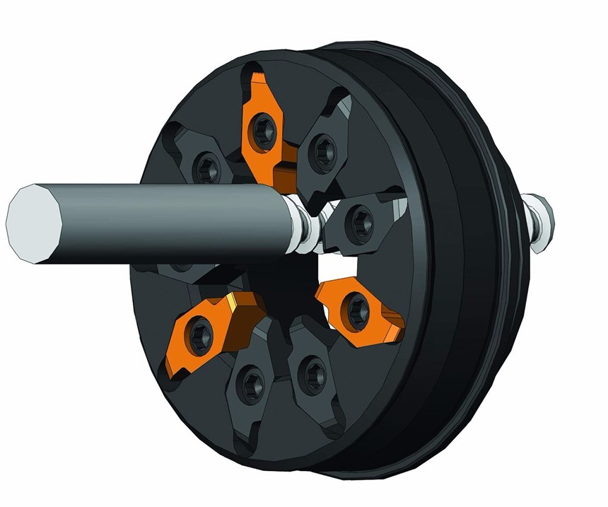
“With the Turbowhirling concept, Horn sets up the tool using roughing and finishing inserts. The roughing inserts do the majority of the cutting, taking the thread down just short of the finish diameter. The finishing inserts then clean up and cut the threads to their specified depth and profile. Because the finishing inserts are removing significantly less material volume, tool life is increased significantly. The tool body for Turbowhirling is the same as for conventional whirling, as is the cutting data.”
Using this specialized system, the inserts can be designed to better perform each assigned task. The roughing inserts, because they are not generating a functional surface, can be formulated to tolerate quite a bit of wear. This allows the finishing inserts to generate the functional surface with a minimum amount of stock removal, improving their tool life. In effect, the combination of roughing and finishing cutters allows the whirling tool to perform rough and finish operations in a single pass, thus improving throughput.
The arrangement of the roughing and finishing inserts depends on the number of inserts that the cutter can accommodate. On a nine-insert cutter, three inserts might be used for roughing, with six inserts to cut the thread to the final size and finish profile. The seats in the cutter body are standard, so the inserts can be arranged in various ratios to accommodate the application.
For some applications, if the whirling toolholder has sufficient pockets, the cut can be further divided with the use of semi-roughing inserts, effectively combining what would take three passes into one. Increasing tool life is an important goal for this whirling system. Generally, because the finish inserts are removing relatively small amounts of material, the roughing inserts can be indexed three to four times before the finish inserts need to be exchanged.
“Shops that have experience in thread whirling will find that using the Turbowhirling concept is no different,” Mr. Foschaar says. “The difference between the two cutting methods is the geometry and arrangement of the indexable inserts. The roughing inserts are ground for roughing and the finish inserts are ground for finishing. To prevent confusion with building the tool, the roughing inserts receive a flash coat of TiN to visually distinguish them from the finish inserts. It’s a simple, yet effective way to make sure the inserts are positioned in the correct pockets.”
The whirling attachments for Turbowhirling, likewise, are standard. If an attachment can be used for conventional whirling, it will work for Turbowhirling. Moreover, if the attachment can accept a quick-change cutter, they too will work for Turbowhirling tools. “Basically, the only difference between conventional whirling and Turbowhirling is the performance from lowered cycle times and longer tool life,” Mr. Foschaar says.
Rotary Whirling
A presentation on rotary whirling by Mr. Foschaar was another item on the technical agenda during my visit to Horn in May. “Rotary whirling is a new thread production process being developed in the context of the Thread Project by the German Federal Ministry of Education and Research (BMBF),” he says.
Participants in the BMBF project, along with Horn, are Index/Traub medical device manufacturer Smith & Nephew, and the research institute WBK Karlsruhe. This project began in 2014 and is slated for completion at the end of 2017.
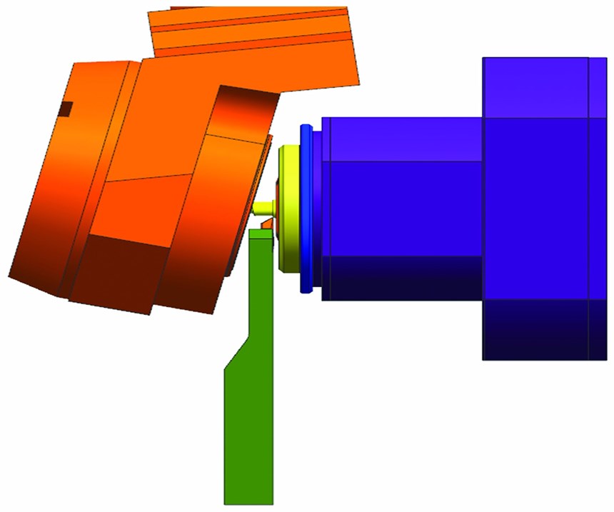
The idea behind rotary whirling is to reduce the amount of material the thread whirling tool needs to remove, resulting in higher production rates. This is accomplished using a single-point turning tool that traverses the blank part ahead of the whirling cutter.
In effect, the turning operation takes the blank down to the major diameter of the thread to be cut. As the whirling tool engages the workpiece blank, it needs to only remove the material necessary to take the part down to the minor thread diameter and generate the thread geometry. This new process, which Mr. Foschaar refers to as parallel turning, results in significantly less metal volume to be removed by the whirling tool and significantly higher cutting speeds, overall.
The plan from the development group is to have the single-point turning tool mounted on one of the gang tool stations of the Swiss-type and is then fed into the work independently of the whirling attachment.
A difference in this new process is that with the single-point turning tool engaged, the speeds and feed for the thread whirling attachment are accelerated from the relatively slow rpm requirements for conventional and even Turbowhirling to significantly higher rotation for efficient turning. According to Mr. Foschaar, “This speed differential can be in the ranges of 9 to 20 rpm for conventional whirling and as much as 2,000-3,000 rpm for rotary whirling in order to efficiently use the single-point cutter.”
In the rotary whirling process, the whirling attachment is synchronized with the spindle speed so that the workpiece rotates once, or 360 degrees, per insert in the whirling cutter. Part of the development work of the BMBF project is to develop whirling attachments that can generate sufficient rotational speed to take advantage of the accelerated cutting capabilities of the process, as most currently available whirling attachments are not capable of these higher speeds.
The rotary whirling project is being tested under real shop conditions with results being analyzed. Experience teaches us that if there is a better way, it will find a home in metalworking shops around the world.
Always Moving Forward
Turbowhirling is ready for prime time. It is a step forward that brings advantages to conventional thread whirling and is commercially available for the right applications.
The results from the rotary whirling project are encouraging thus far. Rotary thread whirling is a significantly more sophisticated process than conventional and Turbowhirling. Calculations to produce the desired thread geometry are unique to each thread, and part of the development process is to generate software for performing these calculations.
It’s a team effort among the participating companies and institutions with each bringing a specialty to the group. Metalworking is moving forward into areas that were not conceivable only a few years ago, and it’s through development programs such as BMBF that development work continues to improve how our industry does its work.
Looking at these two new approaches to thread generation, based on a whirling process that dates to the 1940s, makes one wonder how much more is in the near future as mechatronics (blending mechanical and electronics) continues to march forward. It’s a good time to be in manufacturing.
Related Content
Upgrading Bar Feeder Components with Metal 3D Printing
Index is exploring redesigning and optimizing parts for bar feeders inside its multi-spindle turning centers using a low-cost metal 3D printing platform from One Click Metal.
Read MoreWhere Machining Precision is a Family Tradition
This century-old manufacturer is a case in point of how company culture and openness to adopting new technology paves the way to success.
Read MoreSoftware Controls Chip Breaking in Thread Turning Operations
This cutting tool manufacturer has developed a software module for chip control of thread turning operations in virtually any CNC lathe, even for older machines, using specific tooling and software.
Read MorePMTS 2023 Product Preview: High-Volume Turning
Learn about some of the latest high-volume turning solutions that will be on display at PMTS 2023.
Read MoreRead Next
Take This Tool for a Spin
Turbo whirling is a newly developed process from Horn USA that optimizes machining during thread whirling, boosting both productivity and cost-effectiveness.
Read More5 Aspects of PMTS I Appreciate
The three-day edition of the 2025 Precision Machining Technology Show kicks off at the start of April. I’ll be there, and here are some reasons why.
Read MoreA Tooling Workshop Worth a Visit
Marubeni Citizen-Cincom’s tooling and accessory workshop offers a chance to learn more about ancillary devices that can boost machining efficiency and capability.
Read More


.jpg;maxWidth=300;quality=90)


