A Look at Today's Cast Iron
This article explores a variety of factors affecting machinability of grey and ductile irons. Choosing the right combination of metal and cutting tools can have a dramatic impact on the cost of a part.
Try to imagine a metal that has the strength of steel barstock, but that can be machined into finished components twice as fast with less tool wear. It is 10 percent lighter, can be heat-treated without carburizing and will not distort. It has damping properties that make quieter gear sets, and the cost per pound is about the same as steel barstock. What is it? If you haven’t already guessed, the high-tech metal described above is today’s cast iron.
Often dismissed as a cheap, dirty, brittle metal, cast iron is getting much more attention today because of its machinability, light weight, strength, wear resistance and damping properties. The engineered cast irons of today are much different than they were even 20 years ago because of better understanding of, and improvements in, the processes used to produce them. Continuously cast ductile iron bar stock produced in the United States competes very favorably with low-cost foreign steel bars because of its ability to be machined at speeds in excess of 1,200 surface feet per minute (sfm) with standard carbide inserts. Ductile iron’s mechanical properties are very similar to steel, making it an excellent material for the machinist and the design engineer.
In today’s competitive environment there is constant pressure to lower prices and to improve productivity. Design engineers need to make longer lasting components, but use of stronger, more wear-resistant materials often means increased manufacturing cost. Continuous cast iron barstock can be an excellent alternative to steel, offering a good balance between mechanical properties—such as durability—and machinability.
The Continuous Casting Process
Wells Manufacturing Co. first introduced the process of continuous casting of gray and ductile iron to the United States in the 1960s. The original machines were used to make high quality gray cast iron that could compete favorably with sand castings. However, most of the growth over the past 20 years has been, and for the future will continue to be, converting to ductile iron applications that are predominantly machined from carbon steel bar.
The continuous casting process uses a water-cooled graphite die mounted on the bottom of a bar casting crucible (above). Iron flows into the die and a skin forms taking the shape of the bar. The bar is cast through the die in a series of strokes, 1 to 2 inches in length, pausing between strokes to allow molten iron to enter the die and to form the “rim”; as the bar exits the die, the only part that has solidified is the outer rim. Most of the bar consists of a molten iron core that re-heats the rim above the critical temperature. As the bar extends farther from the die, it eventually solidifies, producing a homogenized microstructure.
Continuous cast iron bar can be produced in many shapes. Cast iron barstock sold under the Dura-Bar trade name is available in round bar up to 20 inches in diameter, rectangles and squares up to 18.5 by 22 inches, and in special extruded shapes.
Some Definitions
Cast iron is a generic term for a high carbon, high silicon, iron alloy. It is similar to steel in that strength, wear resistance, heat-treat response and machinability are affected by the amount of carbon in solution with the iron. Strength and wear resistance increase with the amount of combined carbon; machinability, in general, decreases.
Cast iron is unique in that carbon is added in excess of its solubility in iron at room temperature. During solidification, as the molten metal cools and the solubility limit of carbon in the iron decreases, excess carbon precipitates as solid particles of graphite. A cast iron casting is actually a composite of the graphite precipitate and the solid metal matrix.
The size and shape of the graphite particles are controlled with silicon as an inoculant to “seed” the nucleation of the graphite and to force it out of solution in molten iron. Gray cast iron characteristically has flake graphite and ductile iron nodular graphite, as seen in the microphotographs on the next page.
Cast irons are classified as free machining because the graphite acts as a chipbreaker similar to the way sulfides, phosphides and lead act in resulfurized, rephosphorized and leaded steels. Ductile iron is a natural replacement for leaded steels because it is not toxic and there is no danger of chip disposal harming the environment. Graphite also helps draw heat away from the insert/workpiece interface and reduces friction on the insert during cutting operations. It also makes cast iron 10 percent lighter than steel and offers excellent damping coefficients for gears and other components.
Cast iron’s metal matrix is similar to steel. Its composition depends on the amount of carbon that remains, which is also controlled through proper inoculation. Carbon combines with iron to form iron carbide, a very hard, brittle constituent. As the iron cools, the carbide forms in plates, alternating with plates of ferrite to form a structure called pearlite. Pearlite is much softer than pure iron carbide, but is very wear resistant, has high strength, has some ductility and can be readily machined.
The grades of ductile iron consist of nodular graphite in matrix structures that range from all ferrite to all pearlite to different ratios in between. As the amount of pearlite increases, strength and hardness increase, and elongation and machinability decrease. Ductile iron grades are identified by their mechanical properties: tensile and yield strengths in thousands of pounds per square inch (psi) and elongation in percent. For example, an 80-55-06 ductile iron would have a minimum tensile strength of 80,000 psi, 55,000 psi minimum yield strength and 6 percent minimum elongation.
Factors Affecting Machinability
The harder the material, the more difficult it is to machine, and until recently that was pretty much the extent of what industry knew about machining ductile irons. Tool life tests conducted on a variety of ductile and gray iron grades and on similar grades using different combinations of processing techniques established that a number of factors affect the machinability of ductile iron.
Pig iron and slitter steel in the base melt charges, different types and amounts of silicon inoculant used to nucleate the graphite, and the alloys used to stabilize the pearlite all affect machinability to some extent. In the continuous casting process, the thickness and the concentricity of the solidified rim of the bar are factors, as well as making sure that all processes are in control so that microscopic hard spots from the rapid chilling process are dissolved. Proper control of these factors at the foundry can make it possible for the continuous cast iron bar user to increase turning speeds from 600 sfm to 1,200 sfm with no loss of tool life.
Wells Manufacturing Co.’s Dura-Bar Div. (Woodstock, Illinois) conducted experiments to evaluate the influence of the major processing variables on tool life based in part on tests performed at an independent machine shop. A tool life benchmark was established for the machining of continuously cast pearlitic gray iron. Benchmarks were also established for three grades of ductile iron: 65-45-12 with a hardness ranging from 140 to 187 BHN, 80-55-06 with a hardness ranging from 207 to 229 BHN, and 100-70-02 with a hardness ranging from 241 to 302 BHN. The experiments then tried to determine if tool life could be improved without changing the basic metallurgical and mechanical properties of the materials.
For the tool life tests, 2.375-inch-diameter, continuous cast iron bars were turned into 1.125-inch-diameter, 1.125-inch-long slugs at a speed of 450 sfm, using a 0.125-inch depth of cut and 0.015 inch/revolution feed. The number of slugs, or “parts”, produced per insert was monitored and recorded. Load meter readings recorded during machining and surface finish of the parts were used to determine when an insert had worn out.
In addition to testing processing parameters, the solidification and cooling behavior of the bar affected by casting parameters were studied using a solidification modeling software program designed for the purpose. Computerized modeling of the continuous casting process was used to predict where and when the rim of the continuous cast bar forms inside the die and how thick it will be when it exits the die. Once the die cooler water flow and temperature relationships were established, microstructure evaluation was used to ensure that all microscopic carbides produced by the rapid chilling inside the cooler were eliminated.
Tool life measurements after optimizing each of the processing and casting variables established a 30 percent improvement in parts machined per insert for the pearlitic gray iron bars and the 65-45-12 ductile iron. The partially pearlitic ductile grade 80-55-06 showed an 80 percent improvement in tool life and the mostly pearlitic 100-70-02 ductile iron showed nearly twice the tool life. (Above) The microstructure, hardness and mechanical properties were similar, and the only changes in the process were the raw materials used in the charges, the inoculation alloys to nucleate the graphite and the type and amount of pearlite stabilizers in the die/cooler relationships.
Boosting Turning Speeds
Once optimum tool life was established, the next step was to determine the maximum speed at which a bar could be machined in a lathe without experiencing rapid tool wear. Common recommended speeds for carbide coated inserts on cast iron are less than 800 sfm although machine shops have reported rough machining continuous cast bar as high as 1,400 sfm and finishing at 2,100 sfm.
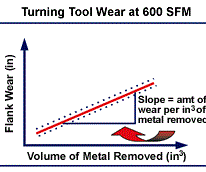
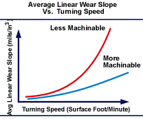
At the University of Alabama at Birmingham, a tool wear test was established to study the amount of flank wear on an insert after machining a specified amount of material using a carbide insert at a given speed. The resulting plot is a linear relationship with the calculated slope representing the wear rate of the material at that speed. Plotting wear rates for a range of speeds produces a wear rate curve and the shape of that line helps determine how fast the material can be machined before the operator experiences rapid tool failure.
Tool wear curves help explain why cutting tool insert manufacturers recommend 800 sfm as a maximum machining speed for cast irons. They also help explain the general reluctance to machine cast iron at high speeds. Below 800 sfm, variations in material heat lots or even variations in material grades do not have much of an effect on tool wear rates. (right) As cutting speeds are increased, however, those variations become critical and must be controlled. It becomes the responsibility of the foundry to make sure all processes are monitored and in control so that a customer will be able to machine as fast as possible without compromising tool life.
Similar experiments to those used in the tool life tests were used to determine the effect of processing and casting variables on tool wear rates. Again, the goal of the experiments was to optimize those variables to produce more machinable grades without changing the basic mechanical or metallurgical properties of the metal. By controlling the critical processing variables that were found to influence machinability, tool wear rates at 650 sfm dropped from 103 mils/in3 to less than 73 mils/in3.
The final cost of the machined part depends on the price of the raw material and on the cost to machine it. Simple machining costs can be calculated by dividing the machine shop rate in dollars per hour by the number of parts being produced per hour. Material cost is simply the weight of raw material being used multiplied by its cost in dollars per pound. It is important to understand the ratio of raw material and machining cost in the final part cost to get an idea of the total part cost savings.
| Initial Cost: | Cost after 20% Machininability Increase: | ||
| Machining Costs: ($50/hr)/(5 parts/hr)=$10/part Material Cost: ($0.50/lb)x(10 lbs metal) = $5/part Total Cost = $15/part
|
Machining Costs: ($50/hr)/(6 parts/hr)=$8.33/part Material Cost: ($0.50/lb)x(10 lbs metal) = $5/part Total Cost = $13.33/part
|
||
For example, suppose five parts are being machined per hour in a shop that has an operating rate of $50/hour and $5 of material is used in each part. The initial cost of material and machining is $15 per part with a cost breakdown of 67 percent machining and 33 percent material. If one extra part could be machined per hour—a 20 percent improvement in machinability—the cost of the part drops to $13.33 because of the increased productivity. The calculations are shown at the top of the preceding page
Finally, selecting the “best” grade of continuous cast iron barstock as a replacement to carbon steel depends on the material property requirements for the application. Because of the graphite nodules, ductile iron tensile strengths are slightly less than those for carbon steels with a similar matrix. However, in cases where the properties of continuous cast iron barstock are suitable for the application, the cost savings potential resulting from the ability to increase machining speeds and the number of parts produced in a given time period make it an increasingly attractive alternative to steel.
For example, the hydraulic bushing shown above was converted from 1144 steel to 65-45-12 ductile iron barstock, resulting in a 30 percent cost reduction. The ductile iron bar costs slightly more per pound than the steel, however the user was able to increase the turning speed from 650 sfm to 1,400 sfm. Cycle time was reduced by 2 minutes without any difference in tool life. The customer did not have to change any other machining parameters. If you have similar parts, it will pay you to explore how switching to today’s cast iron can help your bottom line.
Read Next
A Tooling Workshop Worth a Visit
Marubeni Citizen-Cincom’s tooling and accessory workshop offers a chance to learn more about ancillary devices that can boost machining efficiency and capability.
Read MoreEmerging Leaders Nominations Now Open
Here’s your chance to highlight a young person in your manufacturing business who is on the path to be a future leader moving your company forward.
Read More5 Aspects of PMTS I Appreciate
The three-day edition of the 2025 Precision Machining Technology Show kicks off at the start of April. I’ll be there, and here are some reasons why.
Read More


.jpg;maxWidth=300;quality=90)


