A Primer for Working with 3D Engineering Data
Automation takes many forms in the metalworking shop and one of them is incorporating 3D engineering data into the production process.
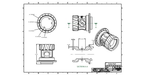
The production machining industry has undergone a number of major changes over the past decade, including increased part complexity, shrinking lot sizes and evaporating lead times. Against this backdrop, one of the paradigms that has helped drive this change has been the advent of 3D engineering data, replacing the paper part drawings the industry traditionally used for quoting, process development and CNC programming.
While the buzzword “paperless manufacturing” has been in the lexicon for some time now, going paperless can just mean replacing paper with digital formats such as PDF that communicate the same data, but without needing to print anything out. Actual 3D engineering data, such as 3D solid models, allows us to work in a truly digital environment, not only eliminating the paper, but the part drawing itself, in many cases.
Virtually every engineering organization world-wide is moving toward 3D modeling of its products, if it hasn’t done so already. As the popularity of 3D design continues to grow, 3D engineering data is going to be pushed down the supply chain more and more, meaning that every participant in that supply chain is going to have to get more conversant and capable with dealing exclusively with 3D engineering data.
This article is meant to be a primer to help understand how to navigate and demystify 3D data exchange for manufacturing. It seeks to explain the basics of 3D design, why engineering organizations are moving to 3D design, what benefits 3D data has for manufacturing, some of the challenges of working with 3D data and how to overcome them to ensure that the organization is working efficiently.
Benefits to Working with 3D Data
The benefits to designing mechanical products in 3D versus 2D are numerous and present a number of benefits to the engineering organizations that create the products that end up being made on a shop’s CNC machines. These benefits include the ability to automate engineering functions, including the creation of full 3D assembly product models as well as performing engineering analyses to ensure the part performs correctly. Additionally, creating a 3D solid model of a part can automate the creation of other engineering documents, including manufacturing drawings and bills of materials.
From a manufacturer’s perspective, 3D data is beneficial because it allows visualization of exactly what the finished product being made will look like. This can be particularly helpful when dealing with complex geometries, perhaps involving a number of rotational and prismatic features that can be particularly difficult to interpret from a 2D drawing alone. Additionally, if an organization has the appropriate CAD/CAM facilities, working directly from 3D data can speed up process development and CNC programming, assuming the data is accurate and robust (more on that later).
Engineering Data Types
It’s important to first understand the different types of digital engineering data that might be encountered. To help better understand the three major components of 3D design, they are explained here in the context of analogy to the human body.
2D Wire Frame. Wire frame geometry is essentially the same geometry used in the 2D drawings that have been around for years. One can think of 2D drawings like the human skeleton. They are very rigid, precise and mechanical, but not very flexible. The most common 2D wire frame format is the DXF file. DXF stands for “Data Exchange Format” and is the standard format for communicating digital 2D design information across a variety of engineering
platforms.
3D Surfaces. 3D surface models show the entire 3D image and shape of an object. However, they do not have any volumetric density. As such, they are very much akin to human skin, in that they are very flexible and malleable but not particularly precise. Typical 3D surface model formats are IGES and STEP files. Unlike the DXF format, the IGES format (often jokingly pronounced “I guess”) is not very standardized and comes in variety of “flavors” depending on the engineering system from which it originated. 3D surface models, particularly those in IGES format, can be particularly dangerous to production machining organizations because they are often inaccurate and provide insufficient information to manufacture a part accurately.
Solid Models. 3D solid models are 3D designs created in 3D solid modeling systems such as SolidWorks, Siemens NX (formerly known as Unigraphics), CATIA, Autodesk Inventor, Creo (formerly known as Pro/E) as well as a number of others. Solid models are akin to the human body. They combine the skeleton (2D wire frame) with the skin (3D surfaces), while providing the “guts” that give the model volumetric substance. These “guts” are typically referred to as “features” in the world of 3D modeling. Each of the 3D modeling systems listed above has its own “native” format, which include all of this feature data in the form of a “feature tree.” 3D models can also be saved in “neutral” or “standard” formats such as STEP or Parasolid, which include*.X_T (Parasolid Transmit) and *.X_B (Parasolid
Binary) file formats.
Pitfalls in Working with 3D Data
Probably the biggest pitfall to working exclusively from 3D models versus 2D prints for CNC manufacturers is a potential loss in precision. While 3D models are great for visualization, they are typically designed using nominal dimensions, which can be problematic if the need is to produce a product to a unilateral tolerance such +0.005/-0. This difference will need to be accounted for when making the part.
Organizations that use 3D modeling systems to design their products will typically provide 3D data in one of the neutral formats mentioned above to their external vendors and partners. When they do this, they are providing a “dumb” model, as opposed to the much “smarter” model that exists when the file is provided in the 3D modeling system’s native format. A good analogy here would be to compare a file created in Microsoft Word with a basic text (*.txt) file. While the text file will communicate all the critical information to the reader, it will lack the formatting of the original Word document.
The other major problem with “dumb” models for those downstream in the supply chain is that they typically cannot be modified because they have been stripped of their “intelligence,” that is, they do not include the “features” that reside in the native 3D model created in the engineering system.
Additionally, when files are saved from their native “smart” format into a neutral “dumb” format, there is potential for data corruption or loss, all of which can render the model less useful to the recipient. Coming back to the Microsoft Word versus text file analogy, imagine a Word file was saved as a text file, but in the process, not only was the formatting lost, but the first letter of every word was dropped as well. Analogously annoying data loss can occur when solid models are translated from one format to another.
So, if dumb models can present problems such as the potential for imprecise data, data loss and the inability for partners to change them because of issues with design for manufacturability, why are they being provided to begin with? The two primary reasons are as follows:
Protecting intellectual property: Product designers invest a great deal in developing the designs for their products. Many companies that design products don’t manufacture every or even any of the components that go into them,
often choosing to outsource them to second party organizations that have more expertise in actually making products. The challenge is that when an organization decides to
outsource its manufacturing, it is taking a risk—the risk of exposing its intellectual property to theft and unauthorized duplication. A great way to mitigate this risk is to provide outsiders dumb models that give you just enough information to make the part, but not enough to easily reverse engineer it and go into business developing the same product.
Getting the best price: Often, engineering data provided to outside vendors is distributed via the customer’s purchasing department, not the engineering department. The goal of the purchasing agent is getting the best possible price. The best way for purchasing to get the best price is to get the most potential vendors to bid on the job. The best way to get the largest universe of potential bidders to submit quotes is to provide the data in a format that most people can read. Providing data in neutral formats such as STEP or XT allows a broader audience to read the data and thus submit a bid.
Solving the Design for Manufacture Problem
So, with all these potential pitfalls, what’s a precision manufacturer to do? One solution we’ve seen a number of shops adopt is to purchase a 3D design system like SolidWorks or CATIA, where they’ve opted for the system that the majority of their customers use (or the one their biggest customer uses) or one their personnel might already know from previous experience. This approach can present a number of challenges for a machine shop, including:
Purchasing a “full blown” engineering system can be very expensive;
These systems are typically developed for mechanical engineers, not manufacturers, so they can be overly complex for manufacturing organizations;
These systems are typically aimed at designing parts from “scratch” rather than modifying existing designs to make them more conducive to manufacturing. Making something “more conducive to manufacturing” might mean eliminating unnecessary cosmetic features from the model or replacing features such as radii with chamfers that require less machining time to create. What this means is that we often see machine shops that go down this route redrawing 3D models for their own purposes to ensure their accuracy and flexibility. In doing so, these organizations are surrendering a lot of the potential time savings in using the customer provided 3D data.
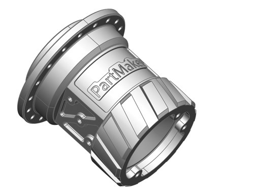
As more of our customers work with 3D data, we’ve seen how these challenges can really slow things down. To overcome these bottlenecks, we’ve introduced our own 3D “modeling for manufacture” system called PartMaker Modeling to help our customer base in the production machining arena cope with these challenges more productively without trying to turn them into product design firms.
PartMaker Modeling is based on Delcam’s PowerSHAPE platform, a well proven system that has been helping moldmakers overcome 3D data creation, translation and manipulation headaches for years. While the system has a number of the same, familiar 3D design tools as systems such as SolidWorks or Autodesk Inventor, it is specifically geared at production machining organizations. As such, it is priced more cost effectively than these systems. Additionally, PartMaker Modeling has some unique technology for manipulating poor quality, inaccurate or just difficult to manufacture 3D data. Specifically, two of these technologies are:
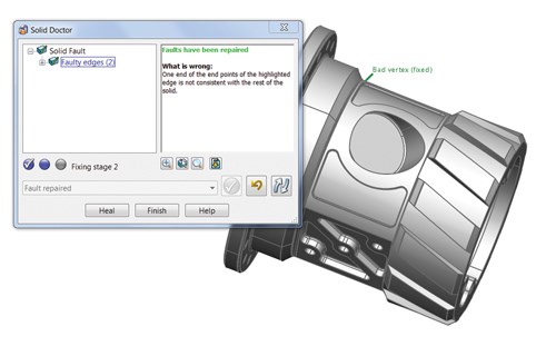
The Solid Doctor: PartMaker Modeling’s Solid Doctor for data repair lets you find and fix faults in imported data automatically.The Solid Doctor works with data from all sources including standard formats like IGES, STEP and Parasolid, plus native files such as CATIA, SolidWorks, Siemens NX and Pro/Engineer. It allows automatic conversion of surface or solid models to perfect Parasolid bodies, well suited for CNC programming in our own or any other CAM system.
Direct Modeling: PartMaker Modeling’s Direct Modeling technology lets you identify, add, remove and edit solid features to “dumb solids” (solid or surface models with no feature history) including adding, removing or changing the size of fillets and/or chamfers and modifying features such as cuts, bosses, pockets and protrusions. Direct modeling allows for creating solid features that can later be modified quickly without having to either rebuild a model’s entire feature history or remodel it from scratch.
The idea of automation in the machine shop is to eliminate costs associated with production. This is equally true on the shop floor and in the programming function. Creating the ability to efficiently manipulate 3D engineering data is a step forward in processing work through the precision manufacturing enterprise.
Related Content
Pursuit of Parts Collector Spearheads New Enterprise
While searching for a small parts accumulator for Swiss-type lathes, this machine shop CEO not only found what he was looking for but also discovered how to become a distributor for the unique product.
Read MoreReplace Repetitive Measurement With DIY Robotic Automation
After minimal training, a shop can learn how to use this robotic inspection system configured for a shopfloor application to supersede repetitive, time-consuming, high-mix gaging processes. It can then be redeployed for another application somewhere else in the facility.
Read MoreZoller Event Shines Lights on Shopfloor Connectivity
The company’s open house event highlighted smart manufacturing solutions from CAM to part.
Read More4 Bright Ideas for Effective Lights-Out Machining
Adopting lights-out machining involves considerations when a machine shop decides to move forward with the process. Here are some tips to a successful implementation.
Read MoreRead Next
5 Aspects of PMTS I Appreciate
The three-day edition of the 2025 Precision Machining Technology Show kicks off at the start of April. I’ll be there, and here are some reasons why.
Read MoreDo You Have Single Points of Failure?
Plans need to be in place before a catastrophic event occurs.
Read MoreSeeing Automated Workpiece Measurement in Real Time
User-friendly inspection software for CNC machining centers was shown at IMTS 2024 monitoring measurements between and after machining while performing SPC based on recorded measurement values.
Read More

