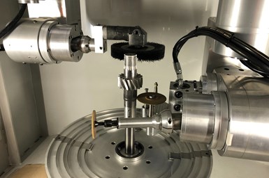
This CNC machine with two, five-axis heads can perform deburring and chamfering operations simultaneously.
Part deburring is one of CNC machining’s inherent necessary evils. How do you handle it? Manually with shopfloor personnel using a knife? Do you program your machining center to do it?
If it’s the former, your machine operators (or other employees) must devote time to that instead of performing other, perhaps more valuable, tasks. Plus, results might vary from person to person. If it’s the latter, then the machine is tied up performing cleanup work when it could be on to heavy milling or turning of the next complex part. And, perhaps worse, swarf or abrasives from deburring operations can work their way down to the machine’s linear guides and ballscrews, which could reduce its positioning accuracy and perhaps eventually bring that critical piece of equipment down for repair.
Vibratory tumbling can be another option. However, this might require masking of vital part features and, for shops with only one such machine, frequent setups because different media might be required for different jobs.
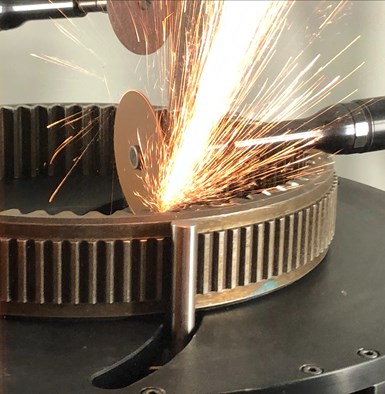
Compliant technology enables deburring and chamfering tools to maintain a constant force on a part as the tools follow part features.
James Engineering in Broomfield, Colorado, offers an automated alternative with its 11-axis Max 5 CNC deburring and chamfering machine that includes proprietary compliant technology to speed and simplify programming, setup and operation.
Gearing Up
James Richards started his company in the early 1980s. At that time, he developed precision deburring and chamfering techniques to finish gears used in Formula 1 race cars. He went on to create hundreds of custom gear deburring and chamfering machines for advanced applications in automotive, aerospace and myriad other industries. The recent development of the Max 5 enables the process to be applied not only to gears and shaft components but to prismatic ones as well.
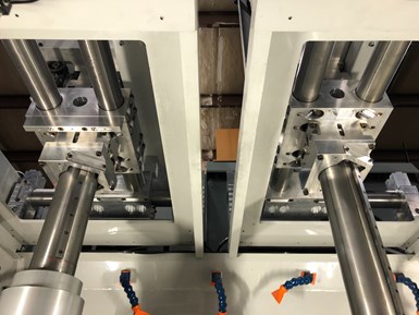
Locating the motion components above the worktable helps ensure swarf and abrasives do not adversely affect its movement. (In this image, the machine’s top enclosure was removed.)
This machine consists of two, five-axis heads and a C-axis rotary worktable. Servomotors position the heads via an X-Y overhead gantry using hardened, chrome, ground shafts and carriers with multiple, preloaded bearings. Movements as fast as 1,500 ipm are possible. Plus, the overhead design means swarf and abrasive material won’t work their way down into the carrier or onto the gantry shafts. In addition, the machine features multiple nozzles delivering water-based coolant with rust inhibitor at 200 gpm not only to keep the part and tools cool during an operation but also to wash the part and machine work zone.
The two heads can perform finishing operations concurrently using various brushes and abrasive tools to minimize overall cycle times as shown in the demonstration video above. Richards also developed a compact 4,000-psi hydraulically driven motor for the heads, providing up to 25,000 rpm using only one moving part and no vanes. Twelve types of tools are available. These install into heads using one bolt.
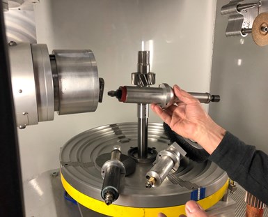
Tools can be changed out of a head using only one bolt.
The heart of this process is the compliant technology, which Richards likens to a car’s front suspension. Using pneumatics and a damping agent enables a tool to maintain a constant force on the part as it follows the contour of the features ahead of it to be finished. This means no change to a programmed tool path is required to adjust for a perishable tool such as a brush that might start at 1.25 inches in diameter and be reduced to 0.75 inch over its life. (Another compliant technology analogy is the way a record player needle follows the grooves in an album.)
This also simplifies programming and setup. Programming the Max 5 is part manual teach-in, part conversational at the machine’s Mitsubishi control. No part solid model is needed. Because of the compliant technology, a tool such as a brush does not have to be positioned as precisely as, say, a cutting tool on a milling machine would. An operator would capture the brush’s initial XYZ coordinates, jog it to the part and record that position (commonly the midpoint of the tool’s range of compliant travel). This is performed for all tools and operations. Values such as feed rate and compliant force are also entered (these vary depending on burr size, chamfer accuracy and more), and fine-tuning of tool positions can be performed as well, if necessary.
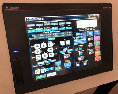
Programming the machine is part manual teach-in, part conversational at the machine’s Mitsubishi control.
Richards says a shop’s best programmer is likely to be the person who has been hand deburring for many years and knows precisely what angle a tool needs to approach a part. The control can store as many as 100 part programs, which the company refers to as “recipes” to distinguish them from the operating program running in the background, it developed for the machine. Individual operations can be chained together much like a word processor’s copy and paste function to further speed programming. Plus, the chosen operations enable what the company calls “focused deburring,” so only those part features requiring such finishing operations are touched.
Read Next
Emerging Leaders Nominations Now Open
Here’s your chance to highlight a young person in your manufacturing business who is on the path to be a future leader moving your company forward.
Read MoreA Tooling Workshop Worth a Visit
Marubeni Citizen-Cincom’s tooling and accessory workshop offers a chance to learn more about ancillary devices that can boost machining efficiency and capability.
Read More5 Aspects of PMTS I Appreciate
The three-day edition of the 2025 Precision Machining Technology Show kicks off at the start of April. I’ll be there, and here are some reasons why.
Read More


