Conformance, Traceability And Measurement Uncertainty In Coordinate Metrology
Customer-supplier disagreements over product compliance to specifications often are costly to the parties involved. Recognition of measurement uncertainty when determining conformance to geometric dimensioning and tolerancing (GD&T) specifications has risen in recent years. This article will focus on some important developments in this arena.
Customer-supplier disagreements over product compliance to specifications often are costly to the parties involved. Recognition of measurement uncertainty when determining conformance to geometric dimensioning and tolerancing (GD&T) specifications has risen in recent years. This article will focus on some important developments in this arena.
GD&T requirements entail the assessment of complex 3D interrelationships of part feature characteristics. To meet this challenge for moderate-sized parts, the coordinate measuring machine (CMM) is a popular tool. Powerful associated data analysis software allows the transformation of raw sample points taken on part surfaces into reportable GD&T parameters such as the parallelism of the cylinders in an engine block. How much confidence can be placed in the values reported by a CMM?
U.S. National Institute of Standards and Technology (NIST) documents make the importance of measurement uncertainty clear: "A measurement result is complete only when accompanied by a quantitative statement of its uncertainty." Ordinarily, uncertainty is expressed as a range of values within which, at a specified level of confidence, the true value of the quantity measured is believed to lie. In CMM-based measurements, a task-specific uncertainty for each and every GD&T parameter is necessary. Required are statements like, "The uncertainty of the diameter of this particular 75.00-mm diameter hole (produced under specific manufacturing conditions) is ± 0.05 mm at 95 percent confidence (when determined with this particular measurement system, using this particular measuring protocol, under this particular set of environmental conditions). As suggested by the parenthetic phrases in the last sentence, many factors will contribute to task-specific measurement uncertainties. The same power and versatility that make the CMM attractive as a measuring device also make assessing these measurement uncertainties a formidable task. First, consider two important roles that measurement uncertainty plays in CMM applications. The first is in measurement traceability; the second is in conformance decisions.
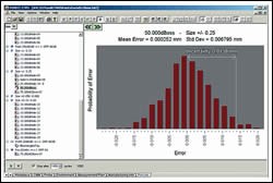
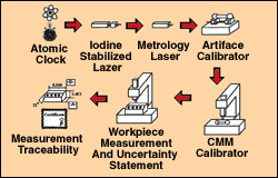
The ISO defines traceability as "the property of the result of a measurement or the value of a standard whereby it can be related to stated references, usually national or international standards, through an unbroken chain of comparisons all having stated uncertainties." The prominent role of uncertainty in completing the traceability chain is evident. Simply having a CMM calibrated does not make its measurement results traceable. If CMM-derived GD&T measurements are traceable, defensible task-specific uncertainty evaluations should be included in a report (see Figure 1).
The importance of uncertainty evaluation has been further emphasized in recent standards (ISO 14253-1 and ASME B89.7.3.1), which create guidance for the decision rule formulation to govern the acceptance or rejection of commerce articles. Figure 2 shows that if a decision rule requires that the specification zone be reduced by the measurement uncertainty to determine the zone of acceptable values, there is a clear economic penalty for greater uncertainty.
Many factors can contribute to the uncertainty in a CMM-based measurement of a GD&T parameter. The number of these influences and the complexity of their interactions have been recognized by experts as making the application of traditional "error budget" approaches to measurement uncertainty largely impractical for CMMs. The ISO 15530 series offers several alternative approaches.
When considering versatility, economy, robustness and comprehensive character, the winner is computer simulation. Here, the part measurement is simulated repeatedly under various conditions. The ranges of factor variability such as CMM geometry errors, sensor errors, environmental conditions, and so on are employed in a mathematical model that allows their influences to be reflected in the resulting GD&T parameter ranges—precisely consonant with the measurement uncertainty concept.
NIST researchers such as Dr. Steven Phillips and his coworkers conceived the statistical method known as "Simulation by Constraints" (SBC). This method recognizes that it is often the case that the CMM user will not have complete and detailed information about errors, for example, in his CMM. In actuality, he may have only an indication from the CMM manufacturer as to maximum permissible errors for a given machine model.
CMM performance data such as specified by ASME B89.4.1 can serve as input to SBC-based software, along with other information about the measurement system (for example, sensor performance test data), environment (for example, thermal conditions of the machine and part) and measurement protocol (for example, surface sampling strategy) for the part. From these data, uncertainty estimates are generated for the desired GD&T parameters. A commercial implementation of SBC technology has been made, giving the CMM user access to assessing the uncertainty of his final reported measurement data.
Because the software evaluates measurement uncertainties by simulation, it is possible to compare the behavior of different CMMs (operating under otherwise identical conditions) to assess their relative abilities to measure any given part, or set of parts, with requisite precision. This is useful when choosing a new CMM for purchase or the right machine for a given job. The user can even see how small his measurement uncertainties might be if he had a perfect CMM. From this, one can recognize how much uncertainty is contributed by the other factors mentioned above. Similar experiments based on a perfect sensor, for example, can identify the weak link in a measuring system, allowing the user to efficiently focus resources on improving measurement precision. Finally, simulation software of this sort is an effective means of training CMM operators and programmers in good measurement practice without tying up valuable CMM time in the process.
— MetroSage LLC
Related Content
Video Tech Brief: Quality Control is Using the Right Software
This machine shop’s mapping software program runs on its gaging system to increase the accuracy of the probe’s tolerance measurement on the thin-walled aluminum tube machined by the shop.
Read MoreAutomated Inspection Transforms Medical Manufacturer’s Quality Control
Manual steps for part inspection have been eliminated with a new CMM process using more advanced software and strategies such as using a combined scanning/touch-trigger probe.
Read MoreHow Well do You Know Granite Surface Plates?
Here are some tips for choosing, maintaining and customizing a granite solution that will best meet your shop’s particular inspection needs.
Read MoreStreamlining Part Measurement, Data Collection Processes
When collecting measurement data automatically with a wireless data collection system, manual errors can be eliminated ensuring data accuracy and traceability.
Read MoreRead Next
A Tooling Workshop Worth a Visit
Marubeni Citizen-Cincom’s tooling and accessory workshop offers a chance to learn more about ancillary devices that can boost machining efficiency and capability.
Read MoreSeeing Automated Workpiece Measurement in Real Time
User-friendly inspection software for CNC machining centers was shown at IMTS 2024 monitoring measurements between and after machining while performing SPC based on recorded measurement values.
Read More5 Aspects of PMTS I Appreciate
The three-day edition of the 2025 Precision Machining Technology Show kicks off at the start of April. I’ll be there, and here are some reasons why.
Read More


.jpg;maxWidth=300;quality=90)


