Grip it on the ID
For many turning applications, gripping on the ID of a center bore can provide processing benefits.
To find out what’s new in workholding, PM sat down with Hank Kohl who heads the U.S. operation for German workholding OEM, Hainbuch America. Mr. Kohl had mentioned to me a while back that he had seen a workholding trend in Europe for turned parts that might be of interest to PM’s readers.
It involves adding the flexibility of gripping on the ID or OD of a workpiece, especially for backworking operations on a secondary or subspindle with the capability to change over in minutes. The ability to choose ID clamping offers several advantages over simply using traditional OD gripping with a chuck or collet.
How We Roll
“Producing parts complete from bar on conventional CNC turning centers with static or live tooled turrets is a traditional approach to manufacturing employed in North America,” Mr. Kohl says. “In these applications the bar is fed out from the main spindle on the machine where the front end turning, drilling or milling operations are performed. The part is then handed off to the subspindle and cut off. Backworking operations are then performed to complete the part.”
Much of the time, the subspindle is gripping an OD section of the workpiece that had been previously machined in the main spindle operation. By holding the workpiece in this manner, access to the part in the subspindle is limited, especially on short parts, because a certain portion of the part OD must be encapsulated in the clamping mechanism in order to hold the part.
The workholding challenge, especially on short parts, is to have sufficient surface area to securely hold the part, have an area that will not be damaged by gripping the OD and still allow for maximum access for the cutting tool. Moreover, for workpieces that require a blended finish turning pass (no witness marks), being able to traverse the entire length of the part can become critical and is restricted with OD clamping.
Accurately cutting non-supported barstock on a fixed headstock truing center is susceptible to the material’s length-to-diameter ratio. According to Mr. Kohl, on an OD collet or chuck this may require the bar to be fed out from the main spindle farther to accommodate clearance for the cut-off tool when the part is handed off to the subspindle. Depending on the amount of clearance needed, this overhang condition can affect the feeds and speed used for machining because of the need to reduce cutting forces that may deflect the part.
Two other points Mr. Kohl makes about the advantage of ID gripping involve no-mar specifications becoming increasingly important for surface finishes, especially in medical applications. Gripping on the ID of a bore rather than the OD can help keep the outside cosmetics of a workpiece more acceptable to a finicky customer.
And secondly, having full access to the entire outside length can aid production shops trying to balance cycle times between operations performed on the main spindle and the subspindle. It’s a goal for most turning production to achieve as close to 50/50 cycle times for op-10 and op-20 as possible for optimum machine utilization and throughput.
Thinking ID
Mr. Kohl says in his experience, about 80 percent of parts machined from barstock have a hole drilled in them as part of the process. By having the ability to clamp on the center bore, the shop has tooling access to the entire length of the workpiece and both ends when using an ID clamping solution.
Another thing that ID gripping helps achieve, especially in the subspindle, is more accurate concentricity between the OD and ID features of the part. Being able to turn the full OD length while the ID is gripped allows any out of roundness from the main spindle operation to be brought back into spec relative to the ID, hence better concentricity.
“The advantages that ID workholding can bring, especially on the subspindle, in my experience, is misunderstood or less understood here in North America primarily because shops here have not been exposed to workholding systems that can deliver these results,” Mr. Kohl says. “I’ve found that when shops did try using ID clamping, often they achieved unsatisfactory results mostly because they tried to use a spring-style ID collet system to clamp on the part, which did not provide sufficient rigidity and clamping strength for backworking operations. Those who were successful with ID clamping tend to use dedicated or costly systems that precluded quick change-over from job-to-job or within families of parts.”
So What’s New?
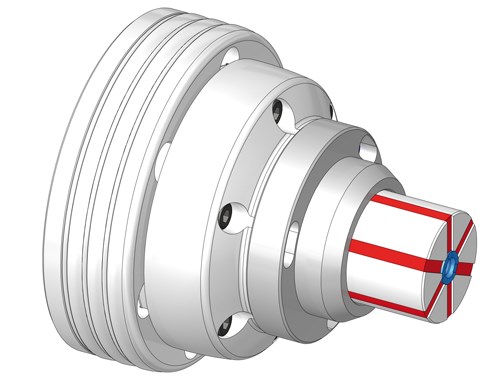
Among the many workholding products that Hainbuch manufactures and distributes, the line best suited for ID gripping on subspindle-equipped lathes is called Mando. It’s similar to the system the company developed for its OD quick-change collet
systems.
“These collet systems differ from conventional system in that they do not use spring steel to hold the part,” says Mr. Kohl. “Spring steel collets require the deflection of the material to create a grip on the part. They effectively provide point contact on the clamped surface.
“Our system uses a vulcanized technology, which allows for independent movement of the segmented clamping elements,” Mr. Kohl continues. “These segments are free to move independently of each other in a parallel clamping motion, which gives full-line or plane contact along the part. Using this vulcanized rubber technology allows for perfect parallel clamping over the maximum surface area to be gripped as well as higher stroke rates in a collet system.”
Originally developed for Hainbuch’s OD collet chucks, the vulcanized rubber system has been applied to ID clamping in recent years. Like the OD system, the ID system uses independent, hardened and ground segments that are free to move relative to each other.
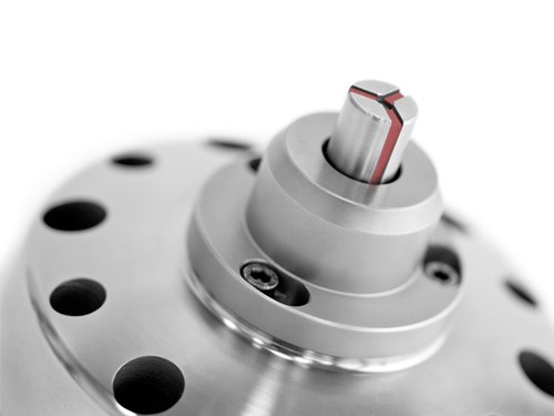
“In the ID system, the independent segments, which we call a bushing, are drawn along a taper, which expands the segments and provides parallel clamping within the bore,” Mr. Kohl says. “This provides the maximum workpiece surface area for clamping and gives fine control over the clamping forces; higher for heavy stock removal or lower for thin-wall applications, but generally lower pressures than conventional collet systems.
“We generally suggest a starting clamp pressure that is 5 times less than traditional systems,” Mr. Kohl continues. “Actuation of the collet is designed to use whatever system is provided by the turning center manufacturer. Most machines use hydraulic via a mechanical drawbar.”
When the bushing is actuated, it is pulled back along
a ground taper. This creates a pull-back effect on the part which secures it against the face stop. Being secured in two planes allows for more aggressive cutting because of added rigidity of the coupling. The system can also be configured for dead-length, if required.
This system is able to accommodate more than straight-line bores. According to Mr. Kohl, the bushing system can clamp in a step, spline, profile or a taper bore. Any of these featured bores as well as straight line holes can be used for location, if necessary. Blind bores can locate off the bottom of the bore or locate off the face of the part with a front-end stop. Datum structure can be transferred using this system as well.
Choices
Modularity is the centerpiece of this quick-change ID clamping system. Increasingly, the need for flexible workholding solutions is driving development of collets and chucks that can be modified to suit demands for relatively high mix, lower volume lot sizes.
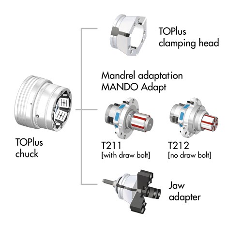
The system mounts directly to the nose of the machine tool subspindle, as a chuck would. However, Mr. Kohl suggests that the shop first mount company’s conventional OD collet chuck in either round or hex versions on both the main and subspindle nose.
“With the OD collet in place, now the shop can run OD clamped work if it wants or it can use an ID adaption unit we provide to accommodate the ID bushing for clamping on the bore parts,” says Mr. Kohl. “For change-over, only the bushing element needs to be changed, not the entire assembly. This is done in a matter of minutes and maintains critical alignments. Working range, expansion rate of the ID bushing technology is approximately 10 percent expansion rate on diameter. So a 10-mm bushing has a range of 10.1 mm. The shop now has in place a system that is able to go from OD clamping to ID clamping within a few minutes. The system does not need to be indicated-in and provides runout accuracies less than 10 microns, typically 3-5 microns.”
There are several configurations designed for workholding within this product line. As an example,
for applications that don’t need the flexibility of both OD and ID clamping, the either collet can be configured to mount directly to the main or subspindle nose in typical flange patterns such as A2-6 or A2-8.
Working range for the ID bushing collet goes down to a minimum ID center bore of 7 mm (0.25 inch). “The bushing system can scale down a little more than 7 mm, but much below 7 mm the rigidity of bushing itself might become an issue,” Mr. Kohl says. “We’ve successfully made them smaller, but it becomes a matter of the part geometry, size and length-to-diameter ratio.”
Know When to Hold ‘em
Movement in this direction is being pursued in Europe
to wring every ounce of efficiency from the metalworking operation which is a reason why these shops are investing in the latest workholding systems available. We see this same effort being put forth by North American precision machined parts manufacturers.
One of the hallmarks of manufacturing is innovation
and workholding systems like Mando represent these advancements. Parts can be machined more profitably if they can be held more productively.
Related Content
German Project Yields Three New Medical Machining Processes
Recent research has resulted in a new mix of high-speed turn whirl milling, polygon turning and rotational turning for manufacturing medical bone screws and out-of-round nails.
Read MoreBroaching Tool Technology For Lathes Used to Slot Inconel Parts
This shop finds value in using an indexable-insert-style broaching tool to create blind-hole slots in heat-treated Inconel aerospace parts on a CNC lathe.
Read MoreReplaceable-Insert Spade Drill Basics, Advantages
Although solid carbide and indexable-insert drills have their place in a machine shop, replaceable-insert spade drills offer specific advantages for various holemaking operations on machining centers and lathes.
Read MoreThe Ins and Outs of Inserts
Understanding how inserts are made provides valuable insight into how their performance can be optimized.
Read MoreRead Next
The Many Sides of Workholding
Here's a broad look at different ways to approach workholding, from bar feeders to collet chucks to robotics.
Read MoreEmerging Leaders Nominations Now Open
Here’s your chance to highlight a young person in your manufacturing business who is on the path to be a future leader moving your company forward.
Read MoreA Tooling Workshop Worth a Visit
Marubeni Citizen-Cincom’s tooling and accessory workshop offers a chance to learn more about ancillary devices that can boost machining efficiency and capability.
Read More


