ID and OD Shoe Grinding for Thin-Walled Workpieces
Studer (United Grinding North America) has a solution to the tricky workholding problem of finish grinding close tolerances for roundness and concentricity of thin-walled rings and sleeves or a rolling element such as a bearing raceway.
Finish grinding close tolerances for roundness and concentricity of thin-walled rings and sleeves or a rolling element such as a bearing raceway poses tricky workholding problems. The surface-profile shape must be extremely precise. Ideally, to achieve these close tolerances, the process should allow machining of both external and internal surfaces in a single clamping. It’s economical to complete the workpiece in a single handling.
At its Motion Conference at the company’s headquarters in Thun, Switzerland, earlier this year, Studer (United Grinding North America) demonstrated its solution to this manufacturing process. One of the demonstrations showed grinding of both the ID and OD of a thin walled blank supported axially and radially by a shoe grinding fixture. This process is called shoe grinding and because it has nothing to do with footwear, the process is also known as microcentric grinding. With this method, the company achieves the customer specified accuracies with throughput that allows medium to high volume production rates, providing an economy of scale that is difficult to achieve with the conventional grinding process.
The Principle
Shoe grinding is a variation of centerless grinding. Using a magnetic plate to support the wokpiece axially while driving the blank along with a set of precision rollers (shoes) that support the wokpiece radially, shoe grinding enables both ID and OD surfaces to be ground in a single setup. Using this workholding system, thin-walled, circular workpieces, such as roller bearing races, can be secured so that it cannot be deformed and so that absolute concentricity from OD to ID is already assured by the workholding system.
These requirements are not met by a jaw chuck (three-, six-jaw chuck), which tend to deform the thin-walled bland, allowing it to “spring back” upon unclamping, which can cause out of spec roundness tolerances. Concentricity between the OD and ID is achieved by machining both the external contour and the internal contour in one clamping.
Likewise, using a magnetic chuck alone for supporting and driving the workpiece blank generally means that each individual workpiece must be centrically aligned manually using a dial indicator, which not only takes a lot of time, but also makes automatic loading impossible. This last point proves to be a major obstacle in the mass production required in the roller bearing industry.
The best way to hold thin-walled rings is to use a method that completely separates the workpiece support from the rotary drive (workpiece drive). The shoe grinding fixture supports the workpiece in two axes; the shoe supports it axially, and the magnetic plate holds it radially and drives its rotation.
Fixture Design
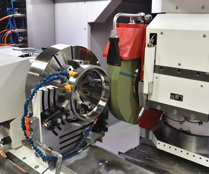
Figure 1 shows a universal shoe grinding fixture. The workpiece has been intentionally omitted to make the design clearer.
In the photo:
- The shoe grinding fixture is clamped to the workpiece table and is movable in Z direction.
- The horizontal supporting shoe is in an oscillating shoe design, with universal sliding inserts with fine adjustment.
- The vertical supporting shoe is in a fixed shoe design, with universal sliding inserts with fine adjustment.
- The electromagnetic chuck is for introduction of the workpiece rotary movement and for fixing the workpiece has radial pole pitch.
- These magnet pole boosters are regularly overground in assembled state, to guarantee the flatness and perpendicularity of the magnet contact surface. They are radially adjustable and clamped in the T-slot.
Studer universal shoe grinding fixtures are available in several usefully graded sizes and cover the diameter range from 10 to 460 mm.
In parallel to the universal shoe grinding fixtures shown, there are also versions for the mass production of part families, which allow quick resetting to a new workpiece using quick-release plates.
Electromagnetic Chuck Design
The electromagnetic chuck drives the workpiece in the direction of rotation, thus generating the workpiece speed. The chuck also holds the workpiece in its nominal position, as it lies against the front surface of the workpiece. A small relative movement takes place here between chuck (pole booster, pole ring) and workpiece end surface, as the supporting shoes position the workpiece eccentrically. Annular pole or radial pole pitches are selected depending on the workpiece size, with the annular pole pitch tending to be used for small workpieces 80 mm and smaller).
Annular pole electromagnets can have different mounting hole patterns, which match a customer’s product range. The driving or holding force of the electromagnetic chuck can be programmed in many different stages. The holding force can thus be temporarily reduced for particularly delicate operations via CNC program commands, enabling stronger clamping afterwards in the same program. The magnetic force can be individually programmed in up to 16 stages on the magnet controller. If several different electromagnetic chucks have to be used, the electrical connection is provided by plug-in contacts directly behind the chuck.
Grinding Head Configurations
The top priority is to finish-grind a roller bearing ring externally and internally: perfect concentricity externally/internally; same manufacturing temperature, so more dimensionally stable; reduction of quantity of “work in progress” (working capital) and so on. The grinding head should therefore be equipped with the grinding tools required for the complete process: external grinding wheel(s), internal grinding wheel(s) and a measuring probe. And naturally on an infinitely variable, high-precision B-axis with a swivel angle repetition accuracy of less than 1 inch is available for Studer S41.
Achievable Accuracies
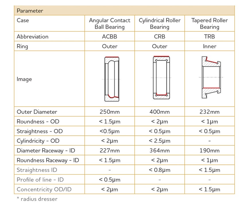
The chart (Figure 3) provides information on what can be achieved with a shoe grinding fixture on a Studer cylindrical grinding machine. These values have been confirmed in various customer projects and internal trials, but the blanks on the system side (frontal surface left) must be perfectly flat.
Shoe grinding allows for high volume, accurate grinding of difficult to hold, thin-walled workpieces. Eliminating the stresses of conventional clamping methods makes this process an ideal solution for such applications.
Related Content
Breaking the Barriers for Small Tool Breakage Detection
This contact-free tool breakage detector, especially useful for machine tools with small tools and small workzones, offers a quick and efficient way to change out broken tools before they cause bigger problems.
Read MoreReplaceable-Insert Spade Drill Basics, Advantages
Although solid carbide and indexable-insert drills have their place in a machine shop, replaceable-insert spade drills offer specific advantages for various holemaking operations on machining centers and lathes.
Read MoreBroaching Tool Technology For Lathes Used to Slot Inconel Parts
This shop finds value in using an indexable-insert-style broaching tool to create blind-hole slots in heat-treated Inconel aerospace parts on a CNC lathe.
Read MoreThe Ins and Outs of Inserts
Understanding how inserts are made provides valuable insight into how their performance can be optimized.
Read MoreRead Next
Do You Have Single Points of Failure?
Plans need to be in place before a catastrophic event occurs.
Read MoreEmerging Leaders Nominations Now Open
Here’s your chance to highlight a young person in your manufacturing business who is on the path to be a future leader moving your company forward.
Read MoreA Tooling Workshop Worth a Visit
Marubeni Citizen-Cincom’s tooling and accessory workshop offers a chance to learn more about ancillary devices that can boost machining efficiency and capability.
Read More


.jpg;maxWidth=300;quality=90)


