One Guide Channel, No Spindle Liners
It’s only 5 years old, but bar feed manufacturer Top Automazioni is growing fast. On a recent visit to the company headquarters in Italy, I found out first hand how technology has developed faster change-over of bar feeders and how it is fueling demand.
Business for automatic bar feeders in general is good. As change-over concerns continue to infiltrate the precision parts manufacturing industry, many shops look to the automation potential of the PLC- or CNC-controlled bar feed unit to augment its production machine tools. The use of integrated control on automatic bar feeders enables them to function in concert with the machine tool rather than be subservient to the machine.
Equipped with magazine loaders that automatically replenish the feeder, these “accessories” can dramatically affect the uptime of capital equipment. On manned shifts, one operator can handle more machines at a time, and for lightly attended or lights-out operations, the carrying capacity of these bar feeders is required to produce the full run.
Bar feed manufacturers continue to do a good job addressing the issues of precision parts manufacturers. Today’s automatic bar feed unit is more reliable and has better range and more flexibility than ever before.
Much development work has been done to help shops change-over the bar feed from one stock size to another. Let’s look at one company’s answer to the problem.
Look Ma, No Guide Channels
The basic function of any bar feed unit is to deliver barstock to the machine tool’s work zone so parts can be cut. In a production environment, long barstock (12 feet) is efficient because numerous parts can be made from a single bar. Add to that the ability to reload the loader from a magazine, and it’s possible to supply material production over a long period of time.
Fundamental to the bar feeder is full length support of the bar as it rotates and a mechanism to push it into the machine as material progressively is used. Bar support is necessary to eliminate chatter that causes vibration and, in smaller diameters, whipping of the material as it is rotated by the machine spindle.
Guide channels are used to accomplish full length support of the bar in the feeder unit. All 12-foot long bar feeds use guide channels, or some variation of them, to support the bar.
The fit between the bar and guide channel is relatively close. Usually, when a bar size is changed the guide channels must also change to accommodate the new diameter or shape. This adds to the downtime of job change-over as well as creating the need to inventory various sizes of guide channels.
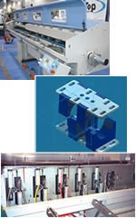
Instead of removable guide channels, Top uses a series of variable position steady rests to support the full length of the bar. They are a U-shaped rubberized plastic material that dampens vibration and noise. The bars rotate while being sprayed with oil inside the steady rests for lubrication.
When changing from one size bar to another, both the upper and lower steady rests move together to keep the bar on the spindle’s center line. Only one complete set of steady rests, comprised of six pairs of upper and lower rests, are needed for the full working range of a given bar feed model and support the entire bar length at all times during the machining process.
The adjustment mechanism for these rests is executed through the PLC input by programming the bar diameter or the maximum inscribed OD for non-round stock. Each new diameter is entered into the PLC, and it calculates the correct adjustment distance of the steady rests for bar diameter and centerline height.
The Pusher As Spindle Liner
Unless the barstock is very close in diameter to the machine tool’s spindle bore, spindle liners are traditionally used to take up the distance variation between bore and bar. These liners, in effect, function as guide channels when the barstock length can no longer be supported inside the bar feeder. Obviously, changing spindle liners and inventorying them adds to the time and cost of job change-over.
Instead of spindle liners, Top uses the bar pusher itself to support the bar once the pusher enters the spindle bore. Basically, this is accomplished by customizing the pusher OD for the specific ID and length of the spindle bore it is attached to. A rotating bearing is fit to the stationary pusher nose for close support in the spindle bore and smooth operation as the bore rotates around the centerline of the pusher.
In effect, once inside the spindle bore, the bearing on the pusher and the collet/chuck on the machine spindle support the bar at both ends, allowing remnant retraction when this option is used. Pushers are interchangeable if the bar feeder needs to be applied to a different size machine.
Hang On To That Bar
Sometimes simple is better. In operation, the barstock and pusher need to be connected. This performs at least two functions.
First, it enables the feeder to precisely move the bar axially within the programmed distance without overshooting. Second, it allows automatic withdrawal of the spindle remnant so no short parts are made and production is uninterrupted. Front or rear remnant ejection can be programmed into the PLC.
For the connection between the bar and pusher, Top uses an “emergency” collet. This collet is made from a vulcanized material that can be quickly bored to the bar diameter needed. A simple, quick disconnect pin secures the collet to the pusher.
The collet grips the bar with sufficient pressure to maintain a solid connection between the bar and the pusher. By keeping a few of these relatively inexpensive collet blanks on hand for when a quick turnaround is needed, the collet can be bored to exact bar size and installed in minutes rather than waiting on a conventional collet to be made or shipped.
It’s About Quick Change
The economics of the precision turned parts industry are changing. This is not news to those involved in the business. Shops today are looking at different metrics to measure the effectiveness of production.
Capital equipment usage is a key measurement for productivity. Cycle time alone is insufficient to gage how well or poorly a job is being run. Today, it is necessary to look at workflow and throughput to get a more accurate picture.
The speed at which jobs can be turned is decreasing and with developments in progress by builders and suppliers as well as shops themselves, this trend will continue. Automation of the production process coupled with quick-change innovation are important cogs in this wheel.
Related Content
Broaching Tool Technology For Lathes Used to Slot Inconel Parts
This shop finds value in using an indexable-insert-style broaching tool to create blind-hole slots in heat-treated Inconel aerospace parts on a CNC lathe.
Read MoreGerman Project Yields Three New Medical Machining Processes
Recent research has resulted in a new mix of high-speed turn whirl milling, polygon turning and rotational turning for manufacturing medical bone screws and out-of-round nails.
Read MoreReplaceable-Insert Spade Drill Basics, Advantages
Although solid carbide and indexable-insert drills have their place in a machine shop, replaceable-insert spade drills offer specific advantages for various holemaking operations on machining centers and lathes.
Read MoreThe Value of Tool Monitoring on Rotary Transfer Machines
By using a tool monitoring system, shops can save costs associated with machine maintenance and downtime for tool changes while increasing cutting performance.
Read MoreRead Next
A Tooling Workshop Worth a Visit
Marubeni Citizen-Cincom’s tooling and accessory workshop offers a chance to learn more about ancillary devices that can boost machining efficiency and capability.
Read More5 Aspects of PMTS I Appreciate
The three-day edition of the 2025 Precision Machining Technology Show kicks off at the start of April. I’ll be there, and here are some reasons why.
Read MoreDo You Have Single Points of Failure?
Plans need to be in place before a catastrophic event occurs.
Read More


.jpg;maxWidth=300;quality=90)


