Rethinking The Multi-Spindle
When the Index MS line, with its open front-end design, hit the streets 4 years ago, it was obviously different. The question is why is it so different? The answer is revealing.
I first saw the MS 32 compact multi-spindle at a show in France several years ago. It was a show stopper then and still is today. I made a mental note then to dig into the machine in detail to find out not only how it worked, but why Index developed such a radical design. Finally, I scheduled a visit to Noblesville, Indiana, to sit down with the company president, Olaf Tessarzyk, to get the answers for my curiosity. It's better late than never.
Form Follows Function
The MS Compact line of multi-spindles was designed to address several issues facing mass production shops. In Europe, the needs were apparent sooner than in the U.S. market, but they are now impacting domestic producers significantly. You know the symptoms: shorter runs, higher mix, tighter tolerances, more complex geometries in tougher materials, shorter lead times and complete machining in a single handling.
An overarching issue, when Index put pencil to paper to design this multi-spindle line, was how to design and build a multi-spindle that can be quickly changed over from one job to the next. It was once good practice to run a large-volume order across a machine and then ship lot quantities as requested by the customer's blanket orders. "The risk to this approach today is that first, you must hold the inventory yourself," Olaf says. "Second, engineering changes to the part you've made can render the inventory as scrap or at best, it would need rework, which can eat up any profit margin for the run.
"In our mind, the basic answer to this problem is the application of CNC technology to the multi-spindle," he continues. "Without the flexibility of CNC, we believe the ability to efficiently deal with changeover is compromised."
Standardization is another design concept brought to the MS Compact line in order to achieve machining flexibility. Many traditional multi-spindles have limits on what operations certain stations can perform. "We took a different approach with this machine," Olaf says. "We looked at each spindle as an independent machining zone. That thinking led us to design and build standard tool carrier units. We gave each unit X- and Z-axis motion and if needed, Y-axis motion. Two of these carriers are assigned to each of the six spindles. Any operation that can be performed on one spindle station can be performed on any spindle position."
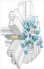
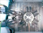
These tool carriers are arranged radially on the headstock end of the machine. Servo-driven actuation of the Z axis is integral to the carrier. The X- and Y-axis actuations are contained outside the work zone behind the headstock casting.
"Each of these tool carriers can perform cross-slide or endworking operations," Olaf says. "What we found as we developed this machine design was that we could eliminate the center tool carrier that is so prominent and large in conventional multi-spindles. This gave us the open front access that is such a significant feature of these machines."
High Accuracy
Another capability the Index engineers wanted to incorporate into the new multi-spindle was high accuracy to process closer tolerance parts. The benchmark for this accuracy came from the company's line of single- and twin-spindle turning centers.
"We wanted to make each spindle station on the MS as accurate as our single-spindle and twin-spindle lathes," Olaf states. "On the multi-spindle, this accuracy target is facilitated by the standardized tool carriers and their ability to operate independently through CNC actuation. This system eliminates accumulated errors from station to station because each station can be individually compensated. It's like ‘mapping' a machine tool. In our case, we can map all six stations."
Generally, there are two critical influences on a machine's accuracy: rigidity and thermal stability. On the MS line, these issues are addressed behind the headstock casting. As we looked at an MS52 on Index's plant floor, Olaf opened the machine covers and gave me a peak at the "core" of this multi-spindle. Inside is the business end of this machine tool.
Each of the tool carriers travels in its X axis on massive high precision round ways. Each of these ways is about 5.5 inches in diameter, and they travel through the headstock casting on hydrostatic bearings. "These bearings are pressurized, which prevents metal-to-metal contact and stick slip," Olaf says.
For additional stiffness, a second parallel way supports a stabilizer arm that offsets any torque induced by the tool carrier. The servo-drive motor and ballscrew actuation for each tool carrier is contained in this core and separate from the work zone of the machine.
The core also contains the spindle drum with its six hollow spindle drive motors, which are 29 kW motors with a top speed of 5,000 rpm on the MS 52C we were looking at. The six spindle motors and six tool carrier motors generate a lot of heat in close proximity.
"Our solution to that is air cooling," Olaf says. "The entire core, including the spindle carrier and tool carrier slide units and their motors, is thermally stabilized with moving air in comparison to water-cooled spindles, where only parts of the spindle are cooled. By isolating the core in an enclosed area, which is positively pressurized by the air, we can control the environment around these key components and keep out ambient influences. This gives us thermal stability, which translates to higher accuracy."
Feeds And Speeds
On the MS Compact line, each of the machine's six spindles has its own programmable motor. "On this machine, it is no longer necessary to compromise spindle speed to accommodate one critical operation out of many," Olaf explains. "Because we approach each machining station (its spindle and two tool carriers) as a single-spindle turning center, individual control of the rotational speed enables use of optimum feed from the tool units. Each spindle runs at its best-performing speed and each has the capability to be stopped without clutches or to be programmed for C-axis rotation. This approach on one spindle, when added together with the other five spindles, permits higher speed production and more complex operations."
But builders who use integral spindle motors in the spindle carrier drum have a problem. The spindle drum indexes unidirectionally in production. The electrical hookups for these motors, however, can't be wound up indefinitely. One solution is to use a circular contact brush to carry the electronic signals from stationary power inputs to the moving collar on the drum.
The MS machine uses direct electrical coupling to the spindle drive motors. This requires that the spindle "rewinds" at the end of each rotation. "We developed and used the contact brush system years ago and found signal transfer and reliability to be an issue," Olaf explained. "Occasionally, the digital signal would be distorted between the control and the motors. We were also concerned about brush wear over time. Pushing six 25 kW signals through the brushes is a lot of power. Although the spindle must rewind, the cycle time impact—an average of 0.1 second—is minimized because the ability to program each spindle's cutting speeds, feeds and changes while indexing generally offsets the time needed for the rewind."
Chucker Or Bar
The original design intent for the machine line was as bar-fed multi-spindle, which, with a bar-loader or feeder, the machine does nicely. However, it quickly became obvious that the open front design provided unprecedented access to the machine's spindles, allowing chucker blanks to be loaded and unloaded using a robot.
In production, a conveyor system delivers blanks to the front of the machine where a machine-mounted robot loads the first position and removes the finished part. It's a fully automated process that can run unattended.
"We didn't focus initially on chucker blanks when the MS Compact was designed," Olaf says. "Index already has a successful line of inverted vertical turning centers for high volume processing of chucker-type blanks. However, the machine used as a chucker, out produces the inverted vertical turning machines. The multi-spindle accuracy is equivalent to an inverted VTL—if not better, and with six stations versus one, many shops are going to look at this machine as an alternative for complex, higher volume workpieces because of efficiency output and labor required to run production. High sales in Europe last year prove this."
Backworking
"If the multi-spindle design has a weakness, it's processing shaft-type parts. The X-axis stroke of the tool carrier limits the length of workpieces to less than 5 inches," Olaf says.
To address the backworking capability, a SCARA (Selective Compliance Robot Arm) is available on the series. It is mounted on one of the tool carrier slides and is, in effect, a seventh spindle for backworking operations. Up to two SCARA units can be mounted on for additional backworking or for loading/unloading and two-part per cycle production.
If an application needs more capability than the MS Compact can deliver, there are two additional machine types of the same modular design available, the MS-P and MS-G, which bring additional capability to the party. They do, however, reduce access from the front of the machine.
Is It For You?
In precision parts manufacturing, the days of dedicated production equipment are fading fast. It is no longer efficient or economical to relegate capital equipment to a single job. "A shop's machine tools must be available to react to the customer," Olaf says. Machine tool builders, like Index, are working hard to bring to market new thinking in machine design and application that helps precision parts makers deal effectively with the new manufacturing realities."
Read Next
Emerging Leaders Nominations Now Open
Here’s your chance to highlight a young person in your manufacturing business who is on the path to be a future leader moving your company forward.
Read MoreDo You Have Single Points of Failure?
Plans need to be in place before a catastrophic event occurs.
Read More5 Aspects of PMTS I Appreciate
The three-day edition of the 2025 Precision Machining Technology Show kicks off at the start of April. I’ll be there, and here are some reasons why.
Read More






.jpg;maxWidth=300;quality=90)

