Rotational Turning Bypasses Grinding
In order to meet close tolerance specifications, most hardened parts are transferred from lathes to grinding machines for final machining. Rotational turning technology, however, eliminates grinding because of special kinematics between the rotating workpiece and a rotating tool.
For applications such as radial seals, bearing surfaces and bearing seats on shafts and axles, the workpieces must be machined absolutely cylindrically and scroll-free (without machining marks). In order to meet these close-tolerance specifications, most hardened parts are transferred from the lathe to the grinding machine for final machining. Rotational turning technology eliminates grinding because of special kinematics between the rotating workpiece and a rotating tool.
Hard turning has long established itself as a machining method to eliminate grinding and its associated high tooling costs, refixturing of the part and relatively long processing times. However, like every technology, hard turning has some disadvantages. One of these disadvantages is caused by the path of the tool during turning operations. Since the edge of the tool moves one unit in axial direction during one turn of the workpiece, the chip is cut off from the surface helically. The depth of this generated groove or twist depends on the construction of the tool, the cutting parameters chosen and the hardness of the machined surface.
Because of this micro-thread or scroll structure on the workpiece, some applications for hard-turned surfaces can be limited. For example, hard turning is not recommended, without a final grinding process, on surfaces below sealings or treads of needle roller bearings. The scroll marks can act as fluid channels on such applications.
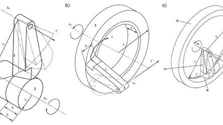
There are several methods available from machine tool manufacturers that accomplish scroll-free hard turning. Rotational turning developed by German builder Weisser Corp., with U.S. operations in Greer, South Carolina, is one of these machining methods. Rotational turning was developed to eliminate the grinding process while creating a twist-free surface on a turning machine.
The starting point for development of these alternatives to conventional turning processes was the elimination of axial feed of the cutting tool, which is the cause the unwanted micro-threads. In contrast to tangential turning operations, where a slanted blade is only linearly moved along the Y axis while the workpiece is turning, rotational turning involves an additional rotational movement of the cutting tool. This tool is better described as a “blade.”
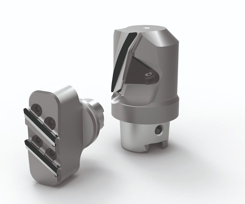
Instead of a single-point turning insert shaped like a triangle, diamond or circle, this rotational turning tool uses a special-geometry straight or helix-shaped blade that vaguely resembles the blade of a turbine. The curve of this cutter presents a slanting edge to the spinning workpiece. Pivoting the tool turret in C axis sweeps this edge across the work, so the cutting action proceeds across the width of the blade from one side of the blade to the other. Depth of cut is 0.1 to 0.2 mm. Since the cutting action gets spread across the blade (not concentrated at a tip the way it is on a conventional turning insert), tool wear occurs much more slowly.
Weisser has developed the rotational turning kinematics in its machine and works with three exclusive cutting tool suppliers who supply the company with blades built to Weisser’s proprietary geometry. According to one of its cutting tool manufacturers, Mapal, the key factor is the large length of the insert. Combined with the contact angle, it gives the Mapal tools an effective machining length of up to 45 mm, with which a surface roughness of less than Rz 2 microns and radial runout accuracies of 3 microns are achieved. The cutter range offers VDI and HSK-T connections in versions as single carrier with one insert or as double carrier with two inserts. The tools can be installed vertically or horizontally, depending on the workpiece.
One example is a gear wheel hardened to 58 to 60 HRC, featuring a root length of 25 mm that needs to be machined. A horizontally mounted single carrier with a HSK-T connection is used. The total machining allowance of 0.18 mm is removed in two working passes. The roughing pass (ap = 0.15 mm) is performed with a feed rate of as much as 0.7 mm and a cutting speed of 200 m/min. The same insert then performs the finishing with 0.4 mm and a cutting speed of 240 m/min. Using conventional turning on this application, feed rates of max 0.1 – 0.2 mm were possible, according to management at Mapal. Tool life was 2,000 parts, and machining time per part was 6 seconds.
Compared with conventional machining, rotational turning allows a reduction in the machining times of more than 70 percent – with higher process reliability and longer tool life, says Mapal and Weisser representatives.
In this example, if the width of the surface to be machined is smaller than or equal to the width of the blade, then the surface is scroll-free, free of twists. If the width of the surface to be machined is larger than the width of the blade, then the OD tool can feed along the Z axis to cover the distance while it pivots in C axis, in which case there are technically micro-threads left. However, both the amplitude and frequency of this surface waviness are much slighter than the lead produced through conventional turning, so the surface is still measurably smooth, the company says.
Weisser is able to offer this rotational turning process for operations that include OD, ID and face turning. Even if freedom from twists is not required, the company says, the processing time is reduced many times over with the new technology—even compared with other soft and hard turning processes. The company approached the development of this process holistically calling upon its in-house expertise in tool blade design, software development and tool carrier design to bring the project to fruition. With up to 77 percent savings potential compared with conventional machining methods, the company believes it is indeed working.
Related Content
Pursuit of Parts Collector Spearheads New Enterprise
While searching for a small parts accumulator for Swiss-type lathes, this machine shop CEO not only found what he was looking for but also discovered how to become a distributor for the unique product.
Read MoreDoes a Scanning Probe Make Sense on a Swiss-Type?
Swiss-types have limited tooling capacity, but there can be advantages to giving up some of that capacity to take advantage of a touch probe — in fact, a scanning probe — to enable in-process part measurements.
Read MoreChoosing the Right Machine for Turned and Milled Medical Parts
The medical market is known for exceptionally tight tolerances and difficult materials, which means that selecting the proper machine is necessary to ensure a job is profitable.
Read MoreSoftware Controls Chip Breaking in Thread Turning Operations
This cutting tool manufacturer has developed a software module for chip control of thread turning operations in virtually any CNC lathe, even for older machines, using specific tooling and software.
Read MoreRead Next
A Tooling Workshop Worth a Visit
Marubeni Citizen-Cincom’s tooling and accessory workshop offers a chance to learn more about ancillary devices that can boost machining efficiency and capability.
Read MoreEmerging Leaders Nominations Now Open
Here’s your chance to highlight a young person in your manufacturing business who is on the path to be a future leader moving your company forward.
Read More5 Aspects of PMTS I Appreciate
The three-day edition of the 2025 Precision Machining Technology Show kicks off at the start of April. I’ll be there, and here are some reasons why.
Read More


.jpg;maxWidth=300;quality=90)


.jpg;maxWidth=300;quality=90)


