5 Tips for Multichannel Programming
Programming for multitasking machines can be complex. Knowing several key points for making the process less challenging can save a programmer time as well as lessen confusion and the risk of error.
Many precision machine shops benefit from multitasking machines, some having multiple turrets and spindles, on their shop floors. The challenge is programming these complex machines.
Many precision machine shops benefit from multitasking machines (some having multiple turrets and spindles) on their shop floors. While these complex machine tools often lead to invaluable advantages — such as reduction in part costs, floor space and setup, increased part accuracy and throughput, unattended operation, the ability to machine parts complete and more — complicated CNC programming presents challenges. Hence, the process usually requires more experienced programmers.
To help simplify the steps for creating the most effective and accurate program, Chris Pollack, international business development manager at Siemens Industry Inc., offers five general tips for multichannel programming. Although Pollack refers to Sinumerik controls to explain some points, these tips are useful on any multitasking CNC, not only on Siemens controls.
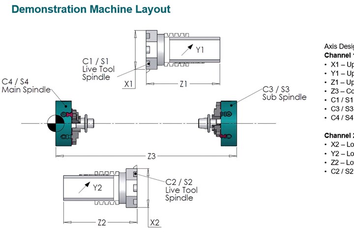
1. Have a defined datum reference from which to build. Most machine tool OEMs reference their datum from the face of the main spindle, according to Pollack. Knowing this simple fact and using that point as the reference for building the program will make the process much easier. When programmers start with a random point within the machine, it makes programming the nesting of parts and transferring parts from the main to the subspindle much more difficult, he explains.
2. Create a cheat sheet that assigns channels to axes. Attempting to remember all the axes inside multichannel machines can be difficult.
Therefore, making a cheat sheet that labels the axes and taping that sheet to the front of the machine can provide a reference for both the programmer and the operator. This is especially useful for operators who move from machine to machine on the shop floor because each machine tool OEM can label its axes differently. Pollack also suggests laminating the information sheet.
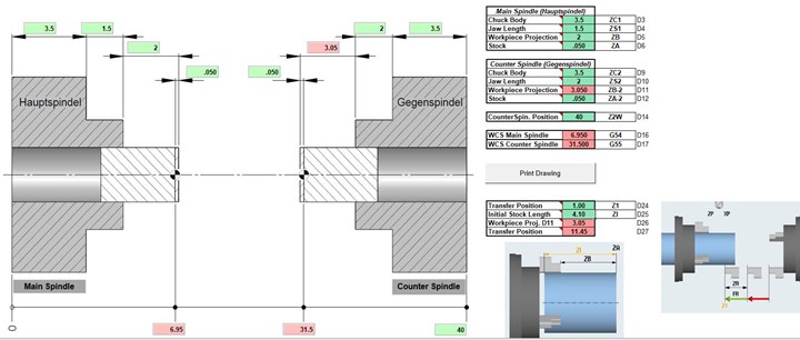
3. Sketch drawings of a specific job’s layout prior to programming. Pollack says he draws the layout of a particular job on a scratch pad. The sketch includes basic block drawings of the part sitting inside the chuck, how far it projects from the workholding, the transfer and where it will end up in the machine. “If you take a few minutes at the front end of the job to figure out the layout, it makes everything much simpler,” he explains. “If you don’t do this, you quickly lose where you are in the space.”
Using this Excel spreadsheet that generates the machine parameters and offsets simplifies the programming process and takes away any guesswork. Photo Credit: Siemens Industry Inc.
Using an Excel spreadsheet that generates the machine parameters and offsets also simplifies the process and takes away any guesswork. Pollack and a colleague created a spreadsheet that enables users to plug in measurements.
4. Use the simplest interface to manage the programs and their specific channels. Sometimes there are two part programs on the CNC, and it is often up to the operator to know which part program is going to run in the correct channel. However, the operator might not know, becomes confused and loads the wrong program into the wrong channel. This mistake can be catastrophic. To avoid this problem, Pollack suggests designing functions into the system that make machine operation unambiguous and more user-friendly.
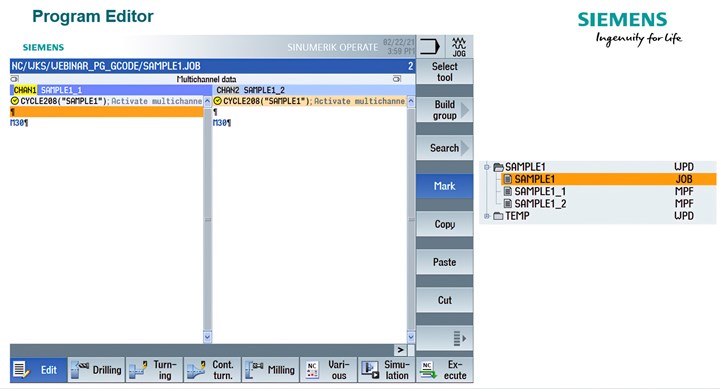
For example, Siemens Sinumerik CNCs offer a function in the sync multichannel programming called the Job List. When the programmer creates the job file, he/she then tells it which program belongs in which channel. This option can be available in the CAM program as well as for shopfloor programming. “Even if you are programming it all in CAM, you can still have the CAM package output the job files and then output the corresponding programs for each channel and the job file,” Pollack explains.
When loading the program into memory, this function will open a Master Editor and load each program into the corresponding channel. Therefore, the programmer can modify part programs simultaneously on one screen, instead of jumping between the upper and lower turret program windows.
With Master Editor, the programmer can modify part programs simultaneously on one screen, instead of jumping between the upper and lower turret program windows. Photo Credit: Siemens Industry Inc.
Most important with this functionality, however, is when the programmer clicks “Execute,” the software automatically loads the appropriate programs in the appropriate channels. Therefore, the operator never has to think about whether the program will run accurately; he/she simply opens the job file.
5. Use wait commands. When there is a program running in the machine’s upper and lower turret simultaneously, wait commands can be added so that one turret waits for the other one to finish. The wait commands enable an operator to pause the machine.
“As you start to get more and more of these commands in, it can be confusing,” Pollack explains. “At what point in time is my upper turret waiting for my lower turret or vice versa?”
He says Sinumerik has functionality in its Editor called Sync View. By choosing Sync View, the program aligns all the wait commands so an operator can see exactly which operation is aligned with which part. Without this function, wait times are listed pages away from each other in the program. Pollack says this can be beneficial because if the operator does not know exactly what part is waiting for what process, he/she can get confused.
“Even if you are not using a Siemens system, look for a third-party editor that has this type of capability,” he adds.
Siemens Industry Inc. | usa.siemens.com/cnc4you
Related Content
Software Controls Chip Breaking in Thread Turning Operations
This cutting tool manufacturer has developed a software module for chip control of thread turning operations in virtually any CNC lathe, even for older machines, using specific tooling and software.
Read MoreShop Sets its Sights on Precise Tool Alignment
A Wisconsin shop has found that visual tool alignment technology has improved tool life and surface finishes for its Swiss-type lathes while increasing throughput as well.
Read MoreWhen a CNC Turn-Mill Doesn’t Turn
A shop in Big Sky Country uses a B-axis multitasking machine to produce complex, prismatic medical parts that require no turning complete from barstock.
Read MoreDoes a Scanning Probe Make Sense on a Swiss-Type?
Swiss-types have limited tooling capacity, but there can be advantages to giving up some of that capacity to take advantage of a touch probe — in fact, a scanning probe — to enable in-process part measurements.
Read MoreRead Next
CNC Apps You Possibly Didn’t Know You Could Benefit From
Some software capabilities go underutilized. One machine tool builder’s CNC software includes lesser-known apps that shops can leverage to their advantage.
Read MoreIntegrated CNC Technology Solutions
Manufacturing is seeing increased integration of product development and production processes with the benefit of innovative, high-performance software systems. This decisive step is an indication of accelerated growth.
Read More5 Aspects of PMTS I Appreciate
The three-day edition of the 2025 Precision Machining Technology Show kicks off at the start of April. I’ll be there, and here are some reasons why.
Read More





.jpg;maxWidth=300;quality=90)

.jpg;maxWidth=300;quality=90)

