Artistry with Skive Tools
Oliver Wendell Holmes said, “All limitations are self-imposed.” This statement often holds true as machinists apply their creativity in skiving applications.
What is skiving, and why haven’t we heard more about it? As my grandfather always explained it to me, “Johnnie, skiving is far less science and far more an art form. A machinist needs to be creative to even begin to think about skiving a part.” In today’s terms, the machinist needs to think outside the box.
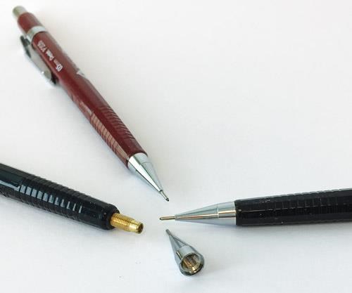
Back in 1962, one of the many newsletters that my grandfather, Lester G. Detterbeck, Sr., penned was focused on skiving. It begins, “The common use of the skive tool is to form the body where its length and contour make forming impractical. One of the common uses back some 20 or 30 years ago (1930 to 1940) was in the manufacturing of tips for automatic or mechanical pencils. The salient feature was that it was possible to do the drilling and tapping with the large end out. Then after the turret operations were completed, the skive tool would come in and finish the shape on the entire tip with the collet end of the tip down to 1/16 inch or 5/64 inch in diameter.”
One might refer to skiving as the secret tool in the bottom drawer of a very good machinist’s toolbox, taken out when all the other options have failed. For me, it has always been an exciting tool that allows one to reach a little further than normal. It’s what makes even the best machinists step back and say, “Oh, that’s cool!”
How it Compares
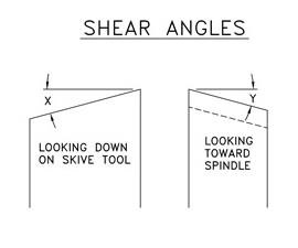
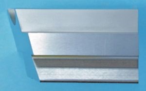
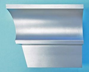
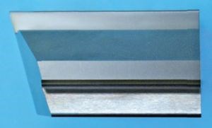
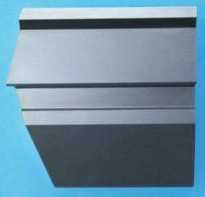
A skive tool is similar to a shave tool in that it passes under (or over) the workpiece. However, unlike a shave tool, a skive tool is normally designed with two angles across its cutting face—a side rake (looking down at the top of the tool) and a front rake (looking from the side of the tool). The double angle works to peel the material away from the part. Where a shave tool normally removes only 0.005 inch to 0.010 inch on a side, a skive tool can remove a fair amount more material.
Unlike a form tool that cuts on the centerline of a part, the skive tool passes under, removing material. In turn, because of its design, the tool supports the workpiece as it goes through the cut. This design allows the skive tool to achieve much larger forming ratios than those of a form tool. A normal, unsupported forming operation can form an area with a width as much as
2 1/2 × the diameter (forming ratio). A supported part might get as much as a 5-to-1 forming ratio (a width 5× the diameter) with a form tool. A skive tool, however, is able to achieve a 5-to-1 ratio on an unsupported part and as much as 8-to-1 when the part is supported. As it runs under the workpiece, it can also burnish the surface, which helps to provide a superior finish compared with that of forming.
Applying the Technology
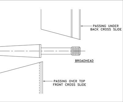
Back in the 1980s, I tooled up a job on a 00 Brown & Sharpe for a firm in Central Illinois that was making broadhead bodies for archery arrows. The parts were made of 1/4-inch diameter 2011 aluminum with a thread on one end. The overall length was 13/4 inches and formed all over. The parts were completely out of the normal forming ratio, so skiving was selected. We were able to use two skive tools and drop the parts complete (less the slots for blades) in one operation. One skive tool was mounted in a 00 Detterbeck skive toolholder on the back slide, and the other skive tool was mounted upside down on a special block mounted to the front cross slide.
My grandfather told me at the time that the operation would not work, but I was a bullheaded young man, and we proceeded with it anyway. This was an application that illuminated the true art of skiving. The back slide skive could be easily adjusted via the Detterbeck holder, but the front slide tool required some fancy shimming to get everything dialed in appropriately. The papers off an old cigarette and a little bit of aluminum foil were used until it was just right. To my joy, the parts ran for years. Every time new tools were ordered I’d smile like Kwai Chang Caine on the TV show “Kung Fu,” having grabbed the pebble from the master’s hand. I think the master was smiling as well, because I had learned the art of skiving.
While many shops use different shear angles on their skive tools, we have settled on two main tools: one set for nonferrous materials (brass and aluminum) and one for free machining ferrous materials. For nonferrous metals, our choice is 23 degrees for both angles, and on the free machining steels, 15 degrees for both. It may seem surprising that these angles match the cutoff angles spelled out by Brown & Sharpe cutoff tool recommendations. Years of trials have proven these angles to be the optimal, but at times other angles do get used.
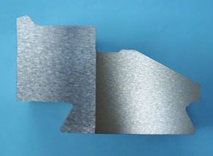
One must keep in mind the travel limits of the cross slides. Using an example of a 0.250-inch diameter being skived 2-inches wide, the throw needed for brass could run upwards of 1 inch. Some machines do not offer that much travel on their cross slides. In those cases, a double angle (arrow point) is used to limit the needed throw or travel. Care must be taken with the arrow point design that the point is designed into a natural geometric change in the part. Skive tools should be mounted to have a slight back taper (0.004 inch) because when they pass under the work, if the slide is worn, the skive tool can bind. With the skive tool tipped up, the apex (point) of the arrow will leave a visible line in the part that may not be acceptable.
Maximizing the Capabilities
As we talk about the art of skiving, we must also be up front about its limitations. The limits for skiving ratios have already been mentioned. Any machinist worth his salt knows that some materials are much freer cutting than others. On parts made of brass or free machining aluminum (2011), skiving can create amazing results, long lengths and fancy, ornate shapes. In steels, caution must be used to steer toward freer machining grades, not blindly approaching the tougher grades with anticipation that the outcome will be the same. Yes, those tougher grades of steel can be used, but with them, consideration must be given to the skive tool material and the angles used on the front of the skive tool.
As with shave tools, skive tools have a problem with producing satisfactory finish on vertical walls, leading to a draft-style design of those walls when tolerances allow. Being limited by the part tolerance, as well as customer requirements, if the tooling is designed with a slight draft, the chip-making action is vastly improved and, in turn, the finish on the wall is also improved.
We have also found that a “sweet spot” exists for diameter reductions—how much a skive tool can reduce a given diameter regardless of the forming ratio. Our rule of thumb on nonferrous is 80 percent and sometimes 100 percent. You say 100 percent? Yes, we once tooled a skive job that skived an entire ball on a screw machine. The job worked great after we added a pin that would remove the ball from the skive tool as it backed away from the cut.
For free machining ferrous, we suggest a diameter reduction limit of half the starting diameter. On a 1-inch diameter part, the maximum reduction would be to 1/2-inch diameter. Anything larger and the skive tool will be forced to take too large a bite to start, and the tool will grab. This issue can be overcome if the diameter first can be rough turned to a smaller diameter, as we did with the broadhead body. In that case, we turned the thread diameter before skiving, so the skive only needed to take the diameter down below the root of the thread.
In brass or aluminum, 0.001 inch for each 0.100-inch stock diameter, with a maximum of 0.004 inch, is a good starting point for feed recommendations. For steel, we recommend starting with a feed rate 50 percent of that used for brass. As always, these are starting points and can always be adjusted as the job is running to optimize production.
We have built skive tools out of high speed steels, solid carbide and carbide-tipped tools. Most recently, we completed a job with insertable carbide tips so the operators could simply plug and play. The key to carbide, whether tipped or insertable, is to make the carbide deep enough so the workpiece doesn’t run past the back side of the carbide. In solid carbide or high speed steel, this doesn’t come into play. Because of the shear angles, the inserts needed to be much larger than the 1/8-inch thick insert that we would normally use for insertable tooling. The machine tool builder who ordered the tooling and their customer are happy with the results.
The limitations of skiving are like a canvas to the Rembrandts of painting—they only push creativity to greater heights. I’m not one to tell machinists that something can’t be done; they will move heaven and earth to prove a statement like that wrong. Skiving may one day be the special tool that saves a job from being a loser, making it a winner. And it will be the creative machinist who dusts it off and makes it work. Then they can stand back and ask, “Do you want your pebble back?”
Related Content
Data Matrix Codes Offer Cutting Tool Traceability
A company’s quest to discover errors in a manufacturing process has led to printing data matrix codes on its cutting tools that provide a wealth of information for both the user and this cutting tool manufacturer.
Read MoreThe Ins and Outs of Inserts
Understanding how inserts are made provides valuable insight into how their performance can be optimized.
Read MoreNew Cutting Tool Technology Discovered at Paul Horn Open House
During a tour of the company’s campus in Tubingen, Germany, I and more than 3,000+ others were introduced to a number of new advances the company has made in cutting tool technology particularly as it relates to the medical industry.
Read MoreShop Sets its Sights on Precise Tool Alignment
A Wisconsin shop has found that visual tool alignment technology has improved tool life and surface finishes for its Swiss-type lathes while increasing throughput as well.
Read MoreRead Next
A Tooling Workshop Worth a Visit
Marubeni Citizen-Cincom’s tooling and accessory workshop offers a chance to learn more about ancillary devices that can boost machining efficiency and capability.
Read MoreDo You Have Single Points of Failure?
Plans need to be in place before a catastrophic event occurs.
Read MoreEmerging Leaders Nominations Now Open
Here’s your chance to highlight a young person in your manufacturing business who is on the path to be a future leader moving your company forward.
Read More






.png;maxWidth=300;quality=90)


