Reinventing The Multi-Spindle's Spindle Drive
Applying CNC to a multi-spindle machine must deal with the problem of independently powering each of the main spindles. A machine, new to the North American market, overcomes this problem with a unique approach.
When you pull back the sheet metal covers and examine the spindle drive system on the Mori-Say CNC multi-spindle, it’s a real forehead smacker—as in “why didn’t somebody think of that before?” ZPS, the brand’s parent company, has devised an elegant solution to one of the knottiest engineering problems involved with applying CNC to a multi-spindle machine.
That problem is how to drive each of the machine’s main spindles, at individually programmed speeds, while allowing them to rotate station to station within the spindle drum. In most cases, this challenge is met by mounting direct drive motors within the spindle drum.
However, this integral drive solution poses a different problem; how to accommodate the power lines to these motors and still allow them freedom of motion as the drum rotates. To date, the most common solutions are to reverse the drum at the end of each 360-degree cycle or employ a slip ring connector to supply power to each motor as the drum rotates.
ZPS has come up with a different approach to the problem. On its Mori-Say line of CNC multi-spindle machines, the company has devised a clever means of mechanically transmitting power to the main spindles from remotely positioned drive motors.
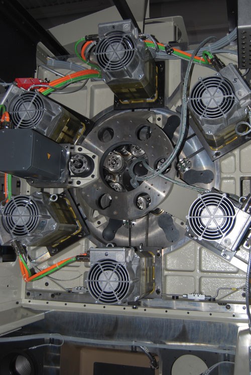
On its six-spindle machine (TMZ 642), Mori-Say drives each main spindle with programmable motors as much as 10.5 kW. These motors mount radially around the centerline of the center block, on the backworking side of the machine, out of the cutting zone.
Because these motors mount outside the workzone and do not rotate with the spindle drum, they are not restricted by space limitations. For example, on the scaled up eight-spindle model (TMZ 867), each spindle drive rated as high as 30 kW. Without space restrictions, these machines can be fitted with a variety of power plants to fit a given application.
At this point, you may be scratching your head. With the spindle drive motors bolted to the endworking side of the machine and the rotating spindle drum located at the opposite end of the workzone, how does power get to the six or eight main spindles? It’s a good question, and the answer is patented.
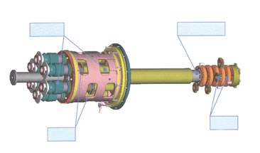
The power transmission from each drive motor to its individual main spindle is via a central drive shaft that runs through the hollow centerline of the center block from the backworking end of the workzone into the spindle drum. Each spindle needs its own drive shaft, but how can six or eight drive shafts run the length of the center block and still allow the spindle drum to rotate in its axis?
The drive shafts run one inside the other, like a folded telescope. The smallest shaft runs inside the next smallest, which runs inside the next smallest and so on. So what you get is six or eight drive shafts on the centerline of one.
Clearance between each reinforced composite drive shaft is 1 mm, enabling each shaft to rotate independently of the others. On the six-spindle machines, these shafts measure from 70 mm to 120 mm in diameter.
On the larger capacity, eight-spindle machine, the drive shaft tubes range from 120 mm to 210 mm in diameter. The ends of each drive shaft run in bearings that mount in stepped seats, one in the spindle drum and one in the backworking casting that support each end of the drive shaft.
To drive the shafts, a bull gear is pressed on the end of each shaft. The OD of the gear is the same for each shaft, and they are arranged side by side (six or eight gears) axially on the assembled drive shaft unit.
Input for each drive shaft comes from the backworking-mounted spindle motors. Each of the fixed-spindle drive motors connects by toothed belt to an idle shaft that runs through bores arranged radially around the tool block centerline.
Each idle shaft has a bull gear pressed on it, and each is aligned in steps to mesh with a specific gear on the drive shaft unit. In operation, each drive motor rotates its idle shaft that is directly coupled to its main-spindle drive shaft. This arrangement allows each spindle motor to be programmed independently and transmit its instructions to its drive shaft. The mechanical connection between the drive motor and its drive shaft is constant.
As for output to the main spindles, a second bull gear is arranged on the spindle end of each drive shaft. The multi shaft assembly, with its bearings and bull gears, is anchored in the spindle drum, which is able to rotate about the drive shaft assembly.
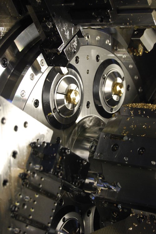
The Mori-Say spindle drum is rather conventional—more like a cam machine than most CNCs. For example, its remotely mounted drive motors do not generate heat in the spindle drum, thus no active cooling is needed.
Chuck or collet actuation devices are unrestricted on the spindles because there is no drive motor interference. Workpiece clamping forces are as good as any cam-actuated multi with the additional advantage of independent spindle programming.
Like all multi-spindle machines, the main spindles are arrayed about the periphery of the drum, creating six or eight positions for cutting. On these machines, each of the six or eight spindle tubes carries a pressed on gear that matches its mating gear on the drive shaft. Each spindle gear meshes with its drive shaft gear and is driven by it.
In constant mesh, the driven gear for each spindle rotates about the axis of its drive shaft gear, enabling the spindle drum to index continuously while all spindles are able to rotate independently. It’s similar to a planetary gear system with each drive shaft gear acting as a sun gear, and its drum-mounted main spindle gear acting as a planet, free to orbit the sun while maintaining engagement.
For shops used to conventional cam-actuated multi-spindles, performance characteristics of this drive system are said to be very similar. The mechanical advantage gained by the geared transmission generates cam machine-like torque. Likewise, the clamping force actuation generated on each spindle is unrestricted and virtually unlimted.
For example, on the 642, its spindle drive motors are rated at 12,000 rpm, but are geared down to run the spindles at 6,000 rpm, maximum. This setup doubles torque right out of the gate.
Shops have the choice of using the machine’s compound slide for single-point turning or single-axis plunging with form tools. The machine has the torque for either.
Moreover, the drive system design allows for varying the pulley ratio between the drive motor and its idle shaft to accommodate more torque to any or all spindles, and likewise, higher maximum speeds based on application requirements.
The spindle drum indexes station to station in about 1 second. Because the spindle drive motors are directly connected to the spindles, programmed speed changes from one position to the next can use this indexing time for free. In other words, speed acceleration or deceleration can be done “on the fly” as the drum indexes, saving cycle time.
With drive motors connected directly to the main spindles, such functions as spindle stop and C-axis orientation are a matter of programming, making the machine capable of turning and milling radially from the compound cross-slides and axially from the endworking positions, all using CNC.
Related Content
CAM-Driven Lathe Questions
There can be hidden issues using legacy cam-driven lathes that can be overcome using new CNC technology. Here are three to keep in mind.
Read MoreGetting More Production From Swiss Turning Centers
Buying a new CNC Swiss turning center is a substantial investment. For the best return, look closely for capabilities that enable the best utilization of the machine.
Read MoreDoes a Scanning Probe Make Sense on a Swiss-Type?
Swiss-types have limited tooling capacity, but there can be advantages to giving up some of that capacity to take advantage of a touch probe — in fact, a scanning probe — to enable in-process part measurements.
Read MoreShop Sets its Sights on Precise Tool Alignment
A Wisconsin shop has found that visual tool alignment technology has improved tool life and surface finishes for its Swiss-type lathes while increasing throughput as well.
Read MoreRead Next
Emerging Leaders Nominations Now Open
Here’s your chance to highlight a young person in your manufacturing business who is on the path to be a future leader moving your company forward.
Read MoreA Tooling Workshop Worth a Visit
Marubeni Citizen-Cincom’s tooling and accessory workshop offers a chance to learn more about ancillary devices that can boost machining efficiency and capability.
Read MoreDo You Have Single Points of Failure?
Plans need to be in place before a catastrophic event occurs.
Read More




.jpg;maxWidth=300;quality=90)
.jpg;maxWidth=300;quality=90)

