Simulation Fascination
One package that was created for the newer generation of Swiss-type machines and lathes is SylvieXpert, developed in Switzerland and distributed in the United States by JuraTech Engineering (Oxnard, California).
The complexity of today’s CNC machine tools has marked the need for ongoing advancements in CAM software. The latest generation of machines handles several channels and multiple axes simultaneously—features that were not even conceived when many CAM programs were originally written. Once a company has invested in the technology that CNC machines can bring, it is necessary to get the most out of it by reducing start-up delays and increasing productivity through efficient programming. This need has prompted CAM software developers to increase the capabilities of the software even further.
One such package that was created for the newer generation of Swiss-type machines and lathes is SylvieXpert, developed in Switzerland and distributed in the United States by JuraTech Engineering (Oxnard, California). The software, currently supporting such machines as Citizen, Star and Tornos TB-Deco Swiss-types and Miyano and Okuma lathes, is entirely based on 3D modeling to provide a full and accurate picture of the machine environment. As an example, from the topology of the part, the software is able to automatically calculate dimensional information for each hole in a part. Therefore, the drill’s tool path will be computer-generated to avoid all collision risks.
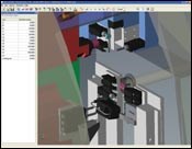
Simulation of machining operations allows complete part programming offline, prior to any cutting, to optimize productivity. While some CAM systems simulate displacements before calling the post processor, this package provides exact simulation based on actual post-processor coding identical to that which will be used by the machine. Generated using CAD files supplied by the machine builders, the simulation shows the complete environment of the machine, displaying any possible collisions with unused tools as well.
To create a new machining project, the user first chooses the machine on which the part will be produced and then defines the shape of the final part. The left window of the display screen shows the elements that make up the project (the 3D models, the local origins, the work planes, the tools, and so on).
Once the software knows the information about the final part, details of the raw material shape must be added. It is possible to use any 3D model as the raw part or to use a simple geometric shape such as a cylinder. The programmer then specifies each step of the machining process on the operating sheet (displayed in the window at the bottom of the screen).
Various simple or complex operation types, such as polygoning, slotting, whirling, 3D finishing, 3D contouring or gear hobbing, can be performed. Each operation type is illustrated by a picture, helping to demonstrate which would be best suited for the application. Depending on the type of operation selected, specific strategies are offered for the lead-in, the lead-out and the machining. The user enters a list of parameters as required by the type of operation. For efficiency, default values can be defined for future use when the same operation is selected.
The software’s tool libraries feature more than 2,000 standard elements as well as the capability to store tools created for previous projects. This method avoids the work of recreating the toolset for each project. Tools are dynamically represented in three dimensions, and models are automatically created from the parameters describing the tool elements.
Once an operation is completely defined, it is displayed in the operating sheet. The programmer must then confirm that the tool is correctly oriented in relation to the workplane used in the particular operation. A tool compensation number then is selected and the operation is calculated. The tool path is displayed in the 3D view and subsequent operations are created to complete the machining of the part. The part can be displayed and, for each operation, the actual state of the part can be shown.
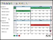
A Gantt diagram graphically represents the operating sheet of the project and allows synchronizations to be implemented to coordinate operations that would be better performed simultaneously. The diagram allows optimization of the part production time, showing clearly the potential idle periods of the process. It also shows an estimation of how long the complete machining process will take.
Collision detection and out-of-travel detection features will automatically pause the simulation of the completed project and highlight faulty elements should problems arise. The user can generate a collision detection report, eliminating the need to watch the entire simulation closely.
One of the design goals of the software was to integrate time-saving features for the programmer. In addition to tool libraries and parameter default values, template sheets allow storage of specific operating sheets and reuse of them in future projects. These stored operating sheets can even be used for similar parts by making changes and updating the shape of the final part.
Added programming features and simulation functionality in today’s CAM packages position users to facilitate the engineering process more efficiently, avoiding the loss of valuable machining time on the programming side. Operators can easily prove out parts offline and be prepared to make them right the first time on the machine.
Related Content
What Is Trochoidal Turning? How Might Shops Benefit From It?
While trochoidal milling might be a more well-known toolpath strategy, trochoidal turning can offer similar benefits such as high material removal rates especially for rough-turning operations.
Read MoreMastercam 2024 Integrates Sandvik Coromant CoroPlus Tool Library
The integrated library enables users to work faster when importing tool geometries and cutting data.
Read MoreVerisurf Probing Suite Provides Flexibility in Quality Inspection
Verisurf’s Machine Tool Probing (MTP) suite is an in-process automated inspection solution for CNC machine tools, offering inspection and reporting capabilities.
Read MoreTezmaksan CAM Software Streamlines Robotics Programming
RoboCAM is designed to eliminate the complexities of robotics programming, making it accessible to operators of all skill levels.
Read MoreRead Next
Software Meets Shop's Multitasking Machine Programming Needs
Structure Medical is not new to the medical supply industry; it is a spin-off of a company called Inovo, which is a manufacturer of oxygen regulators used in hospitals, nursing homes and the like. Inovo’s principals had been looking for growth opportunities.
Read MoreSeeing Automated Workpiece Measurement in Real Time
User-friendly inspection software for CNC machining centers was shown at IMTS 2024 monitoring measurements between and after machining while performing SPC based on recorded measurement values.
Read More5 Aspects of PMTS I Appreciate
The three-day edition of the 2025 Precision Machining Technology Show kicks off at the start of April. I’ll be there, and here are some reasons why.
Read More


.jpg;maxWidth=300;quality=90)


