Understanding CNC Collet Chucks
Workholding for turning is usually fairly basic: The selection comes down to chucks or collets. This article looks at when to consider the collet chuck and what kind might be best for a given application.
(This article is an updated version of the original that was published in 2010.)
When considering the purchase of a CNC lathe or turning center, it is important to ensure that the workholding system is matched to both the machine’s capabilities and the type of work that it will be doing. For example, the workholding system for a large-bore oil-patch lathe that will be machining pipe threads is probably not going to be the right solution for a high-speed multitasking machine making hip joints.
Many CNC lathes and turning centers come equipped from the factory with a standard workholding system consisting of a three-jaw power chuck, a hydraulic actuating cylinder and a drawtube. The hydraulic cylinder is fixed to the rear end of the machine’s spindle, while the chuck is mounted to the front side, or working side, of the spindle. These two components are typically connected together via the hollow steel drawtube that passes through the spindle bore.
The opening and closing of the chuck jaws are accomplished through the axial motion of the hydraulic actuator’s piston. As the piston slides back and forth, the drawtube moves in unison, driving a wedge-shaped plunger within the chuck body. This plunger converts axial motion to radial motion, causing the jaws to open and close. The amount of gripping force that the jaws apply to a workpiece is directly related to the actuator output force and is easily regulated with a pressure valve.
As a universal workholding device, a three-jaw chuck functions well for many common turning applications. It can hold a range of part sizes, is capable of operating at reasonable rotational speeds and achieves good accuracies—particularly when the jaws are bored in place.
A CNC collet chuck mounts to the working side of a CNC lathe spindle in the same manner as a three-jaw chuck and uses the machine’s existing hydraulic cylinder and drawtube for actuation.
However, there are many applications where a jaw chuck is not the best workholding option, which has led to the development of a range of alternative solutions. The most common among these is the CNC collet chuck.
A CNC collet chuck mounts to the working side of a CNC lathe spindle in the same manner as a three-jaw chuck and uses the machine’s existing hydraulic cylinder and drawtube for actuation. The installation of a collet chuck usually requires the fitment of an intermediate adapter between the chuck and drawtube to compensate for thread and position disparities. This adapter is custom machined for the specific lathe/chuck combination and is normally included in the price of the collet chuck.
Small Diameter Parts
CNC collet chucks were originally developed to facilitate the machining of smaller parts. Although collet chucks are available with capacities of as large as about 6 inches, the majority of applications are for workpiece diameters measuring 3 inches or less. In fact, the benefits achieved by using a collet chuck on parts in this size range are so significant, many lathe manufacturers and machine tool distributors now allow customers to purchase their machines with a collet chuck already installed as the standard workholding device.
The most obvious advantage when machining parts in the 0 to 3-inch range is the additional tool clearance provided by a collet chuck’s streamlined shape and reduced nose diameter. This arrangement enables machining to take place much closer to the chuck, providing maximum rigidity and better surface finishes. In contrast, the large diameter of a three-jaw chuck and its jaws typically requires the part being machined to extend further into the work zone, thereby increasing the likelihood of deflection.
Higher RPM
Collet chucks also lend themselves to small diameter work because their lower mass and symmetrical geometries enable them to run at higher speeds than conventional three-jaw chucks. Being comparatively lighter in weight, collet chucks are less prone to the negative effects of centrifugal force and, therefore, tend to produce more consistent gripping force over the entire rpm range.
Tubes and Thin-Walled Parts
One of the major differences between a collet chuck and a three-jaw chuck is evident in the area of workpiece engagement. A jaw chuck typically provides three points of contact—one for each jaw. Conversely, a collet chuck and collet offers 360-degree support. This additional contact helps reduce the chance of part slippage, and also plays an important role in the machining of tubes and thin-walled parts. By distributing the gripping force evenly over the entire workpiece circumference, the risks of pinching and crushing are reduced.
Some additional benefits of using a collet chuck when bar feeding include reduced vibration and faster clamp/unclamp times.
Bar Feeding
Collet chucks are the preferred workholding method for most bar feeding applications. Aside from the previously outlined advantages related to small diameter turning, some additional benefits of using a collet chuck when bar feeding include reduced vibration and faster clamp/unclamp times. The 360-degree contact between the collet and workpiece again comes into play in bar feeding applications by ensuring that the barstock remains on centerline for concentric re-gripping after being advanced by the feeder.
Additional Advantages
Some additional advantages to using collet chucks include faster setup times and/or higher accuracies because there is no need to bore soft jaws in place; availability of standard collets for gripping round, square and hex-shaped stock; internal expanding collets for gripping on workpiece internal diameters; and bores as small as ¼ inch can be accommodated. Holding odd-shaped parts and performing off-center turning are among some of the more specialized applications that can be easily handled with custom collets.
Pullback Versus Dead-Length Operation
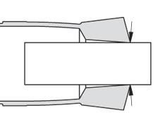
As its name implies, a pullback collet chuck operates by drawing a collet back into the chuck body. As the external taper on the collet makes contact with the internal taper of the chuck, the collet compresses to grip the workpiece. A downside of this simple design is that as the collet draws back, it often starts pulling the barstock or workpiece with it, resulting in variable Z-axis positioning. On first operation jobs, this part movement can usually be remedied with a simple facing cut, but may present more of a problem with secondary operation work or subspindle backworking operations where length features must be accurately controlled.
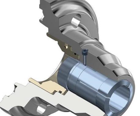
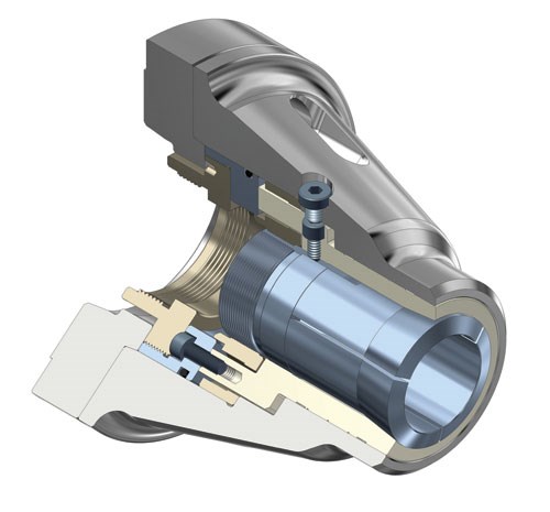
Royal Products’s dead-length collet chucks (branded as Accu-Length) have been designed to overcome the issue of part movement during the closing operation. With a dead-length chuck, the collet is fixed to the chuck body, and a tapered sleeve pushes forward over the collet to compress it. Because there is no axial movement of the collet with this design, workpiece positioning remains constant. As machine tools become more sophisticated with features such as live tooling, multiple spindles, multiple turrets and in-process gaging, there has been a shift in the market away from pullback-style chucks in favor of the more advanced dead-length model of collet chuck for both main and subspindle operations.
Low-Profile CNC Collet Chucks
Royal’s low-profile CNC collet chucks are characterized by both a distinctive streamlined shape and their use of traditional spring-type collets. Collet choices include 5C, 16C, and 3J models, while the larger models use master collets that work in conjunction with S-type collet pads.
With this type of workholding system, the collets have a limited range of a few thousandths of an inch, so it is important to closely match the collet bore to the workpiece size for optimal accuracy and grip force. Installing a spring-type collet into a low-profile chuck is accomplished by threading it into the chuck and engaging a key with the collet’s keyway. Low-profile chucks are available in both pullback and dead-length configurations.
Quick-Change Collet Chucks
Most shops are dealing with short lot sizes across the production spectrum. The days of dedicating a machine to a single long run part are, for the most part, over. The capability for quickly changing over a machine from one job to the next is in high demand.
Workholding manufacturers, such as Royal, have developed quick-change collets (Royal brands its Quick-Grip) in response to this demand. These collet chucks are a relatively new innovation in the workholding market and offer a number of advantages over traditional collet chuck designs. (To read an article about the Quick-Grip collet, visit “Discovering the Benefits of Collet Chucks.”)
Another advantage offered by Royal’s quick-change system is the 1/16-inch gripping range of the collets.
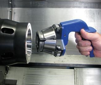
One of the most functional features of this design has to do with the way the collet is installed. A special installation tool compresses the rear end of the collet so that it can be inserted into the chuck. Upon expansion, the collet locks into place via a hook and groove arrangement.
Another advantage offered by Royal’s quick-change system is the 1/16-inch gripping range of the collets. This range is possible because of the fact that each segment of the quick-change collet is completely separated from the other segments by a vulcanized rubber spacer. With this design, all collet segments are installed at the same time.
This design allows for parallel gripping of the workpiece over the entire closing range, providing a significant advantage over spring-type collets where the segments begin to form an angle after being compressed by a few thousandths of an inch. The range and parallel grip of the system enables it to easily handle both oversized and undersized barstock, as well as over-the-shoulder gripping of pins, fasteners, and so on.
One final advantage of the Quick-Grip collet chuck is its extremely short overall length. This provides maximum work zone usage, a benefit that is especially valuable on smaller machines with limited Z-axis capacity. The short length also improves rigidity by keeping the workpiece closer to the machine’s spindle bearings.
Choosing the Right Collet Chuck
Choosing the right collet chuck begins by identifying the spindle nose of the machine on which the chuck will be mounted. All CNC lathe spindle noses follow international standards that clearly define the mounting interface dimensions. Common spindle nose configurations for the North American market include A2-6, A2-8, and 140 mm.
The next step is to determine the chuck’s required capacity, based upon the size of the parts that need to be held. For bar feeding applications, it is customary to match, or slightly exceed, the machine’s drawtube bore size.
Once the spindle mount and required capacity have been identified, the selection can be further narrowed based on specific features and benefits of the various models, including pullback versus dead-length operation; external clearance dimensions; RPM capability; and setup time requirements.
When properly matched to a machine, bar feeder and application, CNC collet chucks provide an economical and effective way of holding material less than 4 inches in diameter. Because collet chucks are generally matched with a bar feeder, some of which have magazine storage and are designed to maintain consistent gripping force at high speeds, they are the workholding choice for lights-out operations.
Collet chucks’ compact size improves tool clearance, maximizes Z-axis capacity and aids in rigidity. Readily available round, square, hex, internal expanding and emergency collets offer broad flexibility.
For more information about choosing the right workholding option for a company, read “The Many Sides of Workholding.”
Related Content
CAM-Driven Lathe Questions
There can be hidden issues using legacy cam-driven lathes that can be overcome using new CNC technology. Here are three to keep in mind.
Read MoreShop Optimizes its Swiss-Turning Flexibility
Paramount Machine uses various Swiss-type lathes, some with a B axis, to produce parts more effectively than it did on conventional chucker lathes. Today, nearly every job under 1.5 inches in diameter runs across those machines even if the batch size is a mere 5 pieces.
Read MoreLaser Technology "Turns" into a Turning Tool
This new technology uses a laser to act as a cutting tool to "turn" parts from solid barstock. This high-speed precision turning machine is especially useful for micromachining, enabling high accuracy for small, complex parts that are often delicate and difficult to machine when implementing conventional turning processes.
Read MoreKeeping Watch on Small Parts
From watch parts to exotic medical applications, this shop takes on the world of micromachining.
Read MoreRead Next
Proper Workholding Selection
An in-depth look at the overall application is the best way to determine the most suitable workholding for a job. Experienced workholding engineers can play an important role in the selection process.
Read MoreCollets Vs. Chucks
Find the definition, types and advantages of both CNC collets and chucks for workholding as well as the best applications for each, in this article.
Read MoreWorkholding For Swiss Turning
In large part, because of the machine’s versatility, Swiss turning is increasing its penetration of the precision turned parts market. As more shops look to this technology, a look at workholding considerations is in order.
Read More



.png;maxWidth=300;quality=90)


