Big Visions for Micro Parts
Micromachined parts place unique demands on dimensional measurement systems. It pays to know the most effective approach for a given application.
Very small parts and features present challenges in part handling, measurement and throughput that require novel technologies. Requirements fall into two broad categories: Small parts that can be measured in a single field of view, and larger format parts with micro features that require high precision and high speed. This article looks closely at two distinctly different types of measuring systems designed to meet these disparate challenges.
Small Parts, Big Challenges
Everything is getting smaller these days—except expectations. It’s become the norm to expect things to get at least 10 percent smaller, lighter, faster and cheaper with every new model year. This constant trend of miniaturization and cost reduction presents some tough challenges for manufacturers. Making things smaller means tolerances are tighter, workholding fixtures are more intricate, and inspection techniques require more precision. Inspection and measurement is one part of the shop where the challenge is particularly acute. This relentless effort to make parts and assemblies smaller requires new technologies to handle production demands.
How Small is a Micron?
There is no single definition of “micro,” and therefore, no single solution for measuring “micro” parts. Micro parts come in a range of sizes and configurations, and process metrology needs to vary accordingly. In general, we classify micro measurements as being between a few microns and a few millimeters, but even that range is enormous, considering that a human hair is about 90 microns in diameter.
Micro-machined parts can be small and simple or small and complex. They can be fragile or solid, expensive or disposable. A common characteristic of micro parts is that they have tight tolerances, so high precision is needed. They also, typically, are made in high volume, so high throughput is needed. The main distinction between types of micro parts might be whether the part needs to be measured with high precision and high speed or very high precision and very high speed.
The choice of measurement technique for micro parts boils down to satisfying the needs for precision and speed to give adequate feedback to the manufacturing process. The choice is not trivial because precision and speed are typically a costly combination. Choosing the right micro-measurement tool for the job is important, and knowing the trade-offs can help.
The Dream
It’s often been said the “ideal” measuring system is a device like a microwave oven. The operator opens the door, places a part inside, presses “Measure,” and moments later a comprehensive measurement report pops out.
Obviously, that ideal scenario leaves out a few practical details, such as creating a measurement program that matches the print, establishing the part’s orientation and datums, obtaining measurements without distorting or damaging the part, and being sure of access to the features to be measured. Still, the concept of the magic measuring box is an appealing one, and it’s coming closer to reality all the time.
The Reality
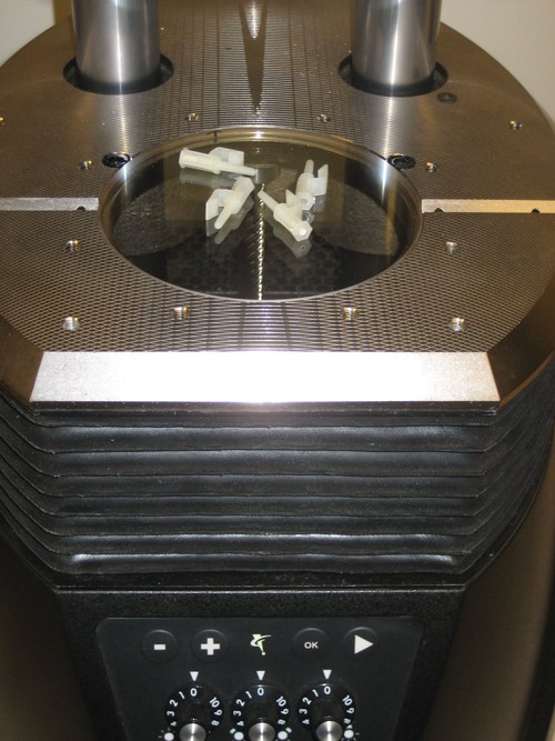
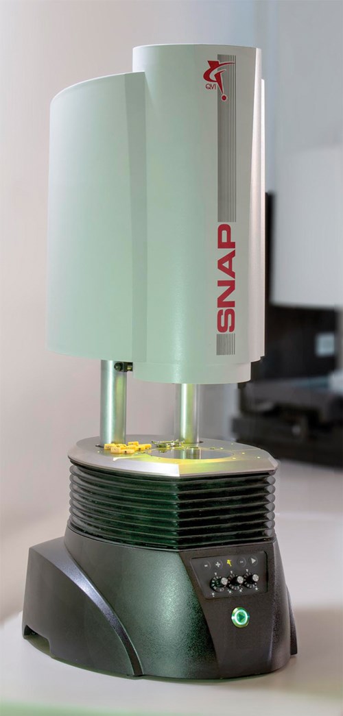
A good step toward an ideal measuring system is the new breed of digital measuring machines, also known as large field of view (LFOV) systems. These optical measuring machines are becoming more accurate and capable of measuring micro parts as digital, megapixel camera, and image processing technology has advanced. For many types of small parts, common dimensions can be measured instantly simply by placing a handful of parts in the field of view and pressing a button. The SNAP system (from Quality Vision International) has an optical field of view of more than 3 inches, enabling multiple small parts to be measured simultaneously. These small parts can be measured instantly by simply placing several of them on the glass surface and pressing the “Run” button. The optics and camera photograph the parts, and the software recognizes them and runs the appropriate pre-programmed routine.
The Three Keys
While it all looks simple, a lot is going on under the hood to make these measurements. The first key to successful micromeasurements with LFOV systems is having a highly telecentric optical system. In other words, the optics must form an image of accurate size, even when the parts have varying thickness or are not perfectly focused. Telecentric optics image accurately throughout their optical depth of field, so they are tolerant of minor variations in focus. The more variation there is in the thickness of parts to be measured, the longer the required depth of field.
Telecentricity is not an absolute concept, and not all telecentric systems perform equally. This can be a challenge for implementing LFOV systems on the shop floor. A moderately telecentric system may display a part image that appears to be in focus, when in reality it is not. If the focus position is not set correctly, bad measurements can easily result. A top quality LFOV digital measuring system has highly telecentric optics. Such capability minimizes size measurement variation and always keeps it within the system’s stated accuracy specs, even when the system is operated by a range of operators, no two of whom will focus the image the same way. The more automatic the focus setup is, the more accurate the measurements will be.
The second key to LFOV measurements is the high resolution, digital, megapixel camera. The added resolution of multi-megapixel cameras allows accurate measurement at a lower magnification than would be needed with a conventional video camera. Thus, the measuring area is larger, and more parts or features can be imaged simultaneously. Where increased magnification is needed for the operator to see very small features (and place measurement tools on them), it is possible to use digital zooming to increase the image size on the system monitor for a closer look. While digital zoom does not increase the measurement resolution, it is a great convenience for observing very small features during program setup.
Another important consideration for micro-measurements using LFOV systems is the measuring software. The latest software for LFOV measuring systems differs from conventional coordinate measurement software in several ways. LFOV system software is designed for easy use on the shop floor, so as many routine steps as possible are made automatic to minimize operations. For instance, the software can perform pattern recognition and auto-correlation to recognize parts in the field of view in any orientation, and automatically load and run their pre-programmed measurement routine. Multiple parts can be counted and measured sequentially, and dissimilar parts can be identified and either measured or excluded from the results. The operator simply puts some parts on the system stage and presses the “Run” button. The software does the rest.
LFOV system software also can make part programming easier by automatically generating a measurement routine based on the part’s CAD design file. Measure-X measurement software from QVI can automatically generate a measurement routine using a 2D CAD file. The operator indicates two alignment features, and the software does the rest.
Finally, to make these systems really convenient for use on the shop floor, the user controls need to be streamlined and simple. A mouse or a touchscreen monitor provides simple controls that are comfortable and easy to activate.
The Need for Speed
Large field of view systems are ideal for measuring small parts that fit easily into their viewing area, but there are other micro applications that don’t fit easily into the LFOV system form factor. Larger parts with micro-sized features, such as micro-electromechanical assemblies, need larger and more precise measuring systems to monitor their in-process dimensional characteristics. When parts are made in high volumes and a large inspection sample size is required, a larger format inspection system is needed to handle these larger lot sizes.
Special techniques and equipment are needed for this combination of micro-feature measurement on larger format parts at high speed. One suggestion is an optical system that allows the user to switch quickly between macro and micro measurements. Conventional zoom optical systems offer the magnification range, but can be a throughput bottleneck if frequent magnification changes are needed. In such cases, the zoom mechanism may need more frequent maintenance or even replacement when systems are used in 24/7 production.
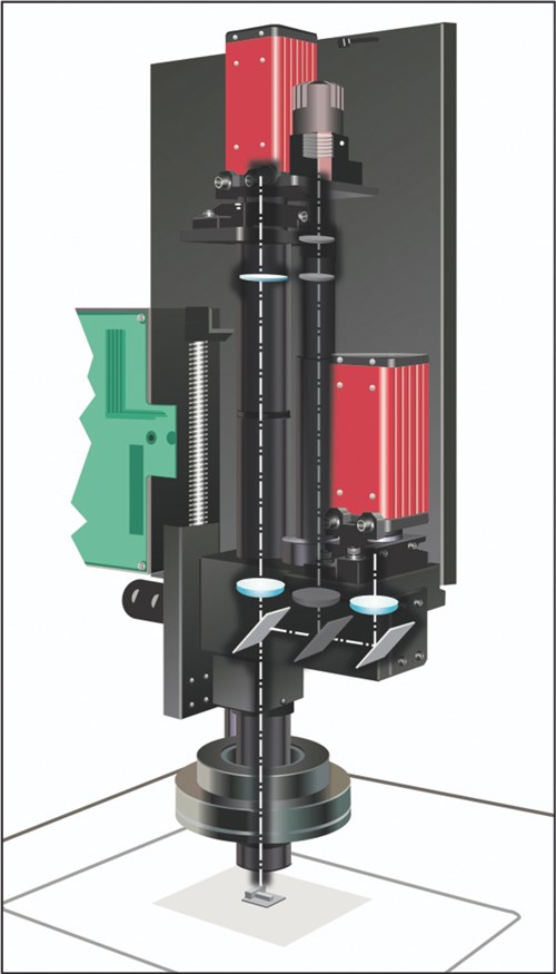
For these kinds of applications, a fixed lens optical system with two (or more) internal magnifications allowing instantaneous magnification change is ideal. The VIEW Summit system from QVI uses this type of system, with two independent internal magnifications and an interchangeable front lens. The internal magnifications are 1× and 4× multiples of the front lens magnification. The fixed lens system design, with no moving parts, ensures constant calibration and high reliability, even in 24/7 operation. This arrangement allows the field of view and optical resolutions to be optimized for the part and feature sizes without sacrificing throughput or adding to cost of ownership.
Another key feature is a high throughput transport system that can convey parts into the optical field of view, or move between measurement sites, at high speeds. Here, the optimum technique to minimize move and measure (MAM) time depends on the part design. When the distance between features is small, the fastest system is one that offers very high acceleration in the X-Y stage motion. When distances are longer, acceleration is important, but overall stage velocity is the bigger contributor to throughput. Where acceleration is the key driver, a system with linear motors offers the best performance. These motors are linear electromagnetic arrays that do not need a mechanical coupling to drive the stage. Being completely frictionless, they are capable of very high acceleration to make short moves in a hurry. The straightness and squareness of axis motion is completely independent of the drive mechanism, too, so the operating speed is a minimal factor in the overall accuracy of the system. Where very long moves and /or heavier loads are involved, a more conventional rotary motor and mechanical drive system offer high top speed and lower overall cost.
An advanced technique for high speed measurement of micro-features is to eliminate the overhead of conventional MAM operations completely by making measurements on-the-fly without stopping the stages at each measurement site. This technique, known as continuous image capture (CiC), requires some special equipment in cameras, lighting and software. The camera frame rate, modulation of the illumination and the velocity of the stages must all be synchronized in order to make continuous measurements as the material being measured is conveyed under the optics. CiC offers the biggest throughput boost when the density of features to be measured is relatively uniform. By selecting the front lens to optimize the number of features in a single field of view and synchronizing the acquisition speed to an integral number of features per frame, throughput can be increased by factors of 4× to 6× compared with standard MAM operation.
Optical Blind Spots
While optics are the fastest and usually the best way to measure micro-precision parts, there are often features that are not possible or not convenient to measure optically. For these, a multisensor system allows alternatives for gathering the necessary data.
One common situation is the need to measure a
dimension inside a hole, cavity or recess that is too small or too deep to illuminate. To measure on the side wall of a hole, for instance, a contact probe would normally be used. But when the feature is too small to probe, one option is a micro-probe with a very small tip radius. OGP’s FeatherProbe is an example of a micro-probe that has a tip radius as small as 1 mm and requires force of less than 10 mg to trigger. This type of probe can penetrate into blind spaces on even very thin or fragile materials.
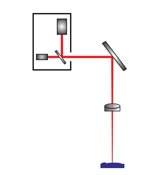
For measuring depths or surfaces that are blind to conventional optics, a laser is the obvious choice, but even the best conventional lasers rely on a reasonable half-angle to return the laser light into the receiving optics. When features are too small or aspect ratio too high to get a strong reflected signal, another option is an advanced tool known as a partial coherence interferometer (PCI). The PCI technique combines data from the sensor beam and a reference source to make absolute depth or height measurements even in very high aspect ratio blind spots.
Meeting the Need
The range of measurement challenges in micro-manufacturing is as varied as the range of “micro” parts being mass produced. Making accurate, repeatable and, above all, fast measurements is vital for process control. With the right tools and techniques, many of the toughest measurement challenges in micro-manufacturing can be handled.
Related Content
Shop Finds Value in Simple CMM Programming
Icon-driven programming enables all shopfloor personnel to perform CMM inspection, not just those in the quality department.
Read MorePrecision Machining Technology Review: November 2024
Production Machining’s November 2024 technology showcase includes some of the latest technology from Vericut, Hurco, the L.S. Starrett Co., LNS North America, Fryer Machine Systems and MachineMetrics.
Read MoreAddressing Machining’s Necessary Evil
Many view quality control as such, but integrating new measurement technologies and approaches can ultimately minimize QC’s impact on throughput and a company’s bottom line.
Read MoreThe Value of CMM Controller Retrofits
In this case, new controllers for two coordinate measuring machines — one 26 years old — with new programming software offers the possibility to enable multisensor inspection of critical, turned aerospace components.
Read MoreRead Next
Dimensional Inspection in the Digital Age
Advanced digital technology has had a significant role in helping shops keep pace with ever increasing customer demands for quality.
Read MoreEmerging Leaders Nominations Now Open
Here’s your chance to highlight a young person in your manufacturing business who is on the path to be a future leader moving your company forward.
Read More5 Aspects of PMTS I Appreciate
The three-day edition of the 2025 Precision Machining Technology Show kicks off at the start of April. I’ll be there, and here are some reasons why.
Read More

