Time will tell, but increasingly, there is evidence that points to the fact that bar-fed mills could well represent the future of complex, small parts manufacturing. To see this coming paradigm shift, one need only walk the halls of the latest IMTS, where a number of major machine tool manufacturers displayed their own, unique offerings of bar-fed milling machines.
Much as the rise in popularity of multitasking, turn-mill centers and Swiss-type lathes made thousands of manufacturers re-evaluate their programming methodologies, a move to bar-fed milling should cause a similar sort of second look at a company’s approach to CNC programming and CAM software selection and usage. Much like a traditional multitasking turn-mill center, programming a bar-fed mill involves more than simply programming milling in one place and turning in another.
However, even the unique approach required for programming turn-mill centers won’t carry over seamlessly to an arena of bar-fed mills. These machines require a unique approach when it comes to CNC programming and CAD/CAM software.
The Function of Bar-Fed Mills
As the name implies, a bar-fed mill is a machine tool that, at its heart, is a vertical machining center, with the important exception that a bar-feeder, similar to that found on a production lathe, is used to introduce raw stock into the working environment. The machining table found on a traditional VMC is essentially a second spindle on a bar-fed mill where work can be handed off after being completed on the primary spindle.
As a result of this important change in architecture, these machines can achieve the continuous production of a bar-fed turn-mill or Swiss-type lathe, while offering all the machining benefits of a VMC—for example, large tooling carousels and milling horse power. The bar-fed approach also provides two major benefits compared with traditional VMCs: It introduces the possibility of turning into the setup, and eliminates the need for the often tedious process of workholding for small parts manufacturing.
In many cases, bar-fed mills have small footprints, making them true “machine shops in a box.” They are ideal for parts in the 15- to 80-mm diameter range and thus are well suited to the medical device, aerospace, fluid power and other critical tolerance markets that require small parts. In a certain sense, because these machines perform machining from a milling spindle, they are much faster to set up than a traditional turret-based production lathe or Swiss turning center, making them ideal for short run manufacture of complex, small components. For many manufacturers seeing the new trend of “in the month, for the month” orders for parts of ever increasing complexity, such machines could be the ideal tool for meeting this demand in their business.
Of course, all this capability has to be considered by the CAM system and presented to the programmer in both a robust and intuitive manner to allow him to take advantage of the capability such machines provide.
Turn + Mill ≠ Bar-Fed Milling
As bar-fed mills can accommodate both turning and milling operations in a single setup, one shouldn’t make the mistake to assume combining a seat of milling CAM software and two-axis turning software will be sufficient to program these machines efficiently. In reality, bar-fed mills will generally perform turning interspersed with a variety of milling possibilities, from indexing on the face and diameter of the part to polar and cylindrical interpolation.
In many cases, even though a part generally starts from round stock on these machines, it may never even see a turning operation, except for perhaps a cut-off operation to transfer the part to the subspindle. A number of bar-fed mill models do not perform turning, and even for the ones that do, very few have the ability to turn on the second spindle, thus cut-off operations are often performed by milling or sawing rather than turning.
PartMaker CAM software deals with the challenges presented by this range of turning and milling possibilities in two ways. From a toolpath processing perspective, PartMaker employs a “divide and conquer” programming approach, which lets the user break down a part into a series of simpler operations. The programmer can then consider each operation in relation to the coordinate system in which it will occur and the tool motions it will require automatically.
Based on the selection of a given “face window,” the software will automatically establish the plane being used for a certain aspect of the part and will restrict the type of machining that can be done to the mode of operation designated in that face window.
When programming a bar-fed mill, it’s not just a matter of mill then turn, or turn then mill. Often there is alternation—a little bit of turning, followed with some milling, perhaps followed by some more turning and so on. However, the decision on an exact order of operations may not occur until the very end of the part processing exercise. To make this non-sequential way of working easier, PartMaker employs a Process Table that allows the programmer to quickly shuffle operations into the exact sequence needed to see them executed, regardless of the order in which the operations were actually created.
Five-Axis Simultaneous Machining
Adding another degree of difficulty for programming bar-fed mills is the ability to perform five-axis positioning and five-axis simultaneous machining. Taking advantage of this capability requires an equally powerful CAM system that supports the virtually limitless programming capabilities five-axis milling introduces.
Part and parcel to the need to support the programming of five-axis simultaneous milling is the ability for a CAM system to support the creation and perhaps, more commonly, manipulation of 3D solid and surface geometry. Very often, the data that comes with a solid model is not sufficient to perform efficient five-axis machining, as it may require certain geometry such as “drive curves” to be added to the engineering model for better five-axis machining. Thus, it is critical when looking to undertake work involving five-axis simultaneous machining on a bar-fed mill to have either a 3D CAD system capable of altering geometry accordingly, or make sure their CAM system has a powerful enough CAD function to allow this.
Simulation
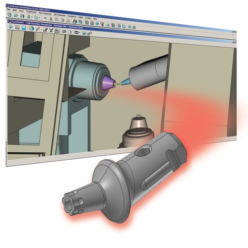
To achieve their machining capabilities, bar-fed mills offer some unusual kinematic machine architectures. For example, one common feature of popular offerings of such machines is an “inverted” second spindle, where the work is held vertically, horizontally and degrees in between with respect to the machining spindle, rather than only horizontally as is usual for the second spindle of a traditional turn-mill center or Swiss-type lathe.
These relative movements really need to be seen to be appreciated, but waiting until you get to the machine to do so may often be too late and cause excessive machine set up and prove out time, thus rendering short-run work significantly less profitable. A CAM system for these machines needs to be able to simulate their unique architectures to allow the user to prove-out the process visually before sending a program to the machine to ensure the setup goes as quickly and efficiently as possible.
Post Processing
Any discussion about the effectiveness of CAM software for a given application needs to end with a discussion about post processing. Without an accurate, flexible and well supported post processor, many of the benefits a CAM system could offer for programming bar-fed mills will fall by the way side. If considering a move to bar-fed milling, make sure your CAM vendor has experience in developing post processors for such machines.
A Case Study: The Angulated Abutment
An example of a class of part that is ideal for manufacturing on a bar-fed mill is a part often found in the dental implant industry. It’s called an angulated abutment, an implant used in dental surgery characterized by the angled component of its design in relation to a straight shaft.
For many years, dental implant manufacturers have vacillated back and forth between making such parts on Swiss lathes and five-axis mills. The advantage of making them on five-axis mills is that the complex geometry of these parts can be more easily machined on a mill. The disadvantage of this approach is that the small size of these parts creates workholding challenges and can thus be less efficient for large quantities. To the flip side, making such parts on Swiss lathes can be more productive for larger volume production, but presents other challenges.
One challenge in making an angulated abutment on a Swiss lathe typically requires the use of an angled attachment, and in some cases a number of such attachments for a single part. These attachments can be both costly and challenging to set up.
Also, Swiss machines generally do not have full five-axis simultaneous machining capability, so the complexity of the part geometry can be limited by choosing the Swiss platform for parts of this nature.
The bar-fed mill can make manufacturing such a part in smaller volumes a more viable proposition because the bar-fed mill does not require any special attachments to program angled milling. However, like the Swiss application, with the bar-fed mill approach, angulated abutments can be made in a higher volume more productively and with less part handling than the traditional machining center approach.








.jpg;maxWidth=300;quality=90)


