Fully Automated Part-to-CAD Measurement Verification
This digital optical comparator was designed to alleviate concerns with traditional optical comparators, and in return, provides fully automated verification of a part against its CAD data.
The complex geometries of parts that are produced in today’s shops are known to have tight tolerances that require highly detailed measurement for quality control. But to stay competitive, shops need to make sure these inspection operations do not add unnecessary time to the production process.
Optical comparators, or profile or contour projectors, are often used to verify that these manufactured parts are within tolerance. They provide a comparison between a part and its drawing to allow the operator to make an overall pass/fail determination. These instruments are easy to use and are well suited for use on the shop floor as well as in metrology and QC labs.
While these measuring tools are generally considered to be versatile and cost-effective, their dependence on an overlay (also called a template or Mylar) can be viewed as a drawback. Besides the added cost and time for printing, calibration and setup, these overlays can increase the likelihood of operator error.
Going Digital
The VisionGauge digital optical comparator was designed to alleviate possible concerns with traditional optical comparators. Developed by VISIONx and distributed in North America by Methods Machine Tools Inc., the instrument uses a high-resolution digital camera and a low-distortion telecentric lens to capture a high-resolution image that exactly matches the part geometrically. The instrument’s software then projects the images, along with the part’s CAD overlay, onto a quad monitor display.
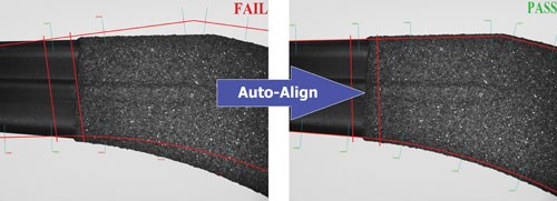
The software’s Auto-Align tool automatically aligns the CAD data to the part. The tool typically takes less than 2 seconds to produce its result, and its operation is very straightforward. Auto-Align produces repeatable and accurate results that are completely operator-independent. It supports both XY and XY-rotation alignment of the CAD drawing to the part. The automated functionality helps users to reduce inspection times and obtain increased accuracy, lining the CAD drawing up with the part along one or multiple data points or doing an overall “best fit” alignment.
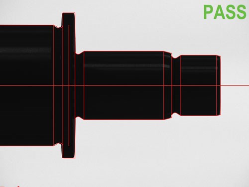
The geometry-based Auto Pass/Fail tool verifies that the part is within tolerance over complete geometric entities.
VisionGauge’s Auto Pass/Fail tool automatically determines, accurately and in real-time, if a part is within tolerance. It can be point-based or can consider complete geometric entities, and it can perform both operations simultaneously on the same part. In point-based mode, the part’s deviation from nominal is evaluated at precise user-specified cross-sections to verify that the part is within tolerance at all of these locations. The geometry-based Auto Pass/Fail tool verifies that the part is within tolerance over complete geometric entities. It supports bi-directional tolerances and imposes no restrictions on the tolerance values. Therefore, tolerances can be either the standard “plus/minus” tolerances or “minus/minus” and “plus/plus” tolerances.
“We are very excited about the release of these new CAD Auto-Align and Auto Pass-Fail tools to enable the fully automated verification of a part against its CAD data,” says Patrick Beauchemin, VISIONx president. “These innovative new tools have been extensively validated at key customer sites, and all of the early adopters are delighted with the benefits that these new tools provide.”
Saving Time
The VisionGauge digital optical comparator can act as a fully digital, drop-in replacement for a traditional optical comparator. It works directly with the part’s CAD data and doesn’t require any overlays, Mylars or templates. The comparators are available in industry-standard 5×, 10×, 20×, 50× and 100× magnifications. Systems are Windows-based and deliver a network-ready “rolling cart” configuration for ease of use on the shop floor. Built for speed and accuracy, the comparators can be set up to automatically collect complete electronic documentation and device history.
Because the systems are software-driven, all operations can be automated. As a result, it is possible to operate the system using only a bar code reader and
Built for speed and accuracy, the comparators can be set up to automatically collect complete electronic documentation and device history.
a joystick, increasing productivity. The digital optical comparator’s camera produces a digital image that is sent to the system’s on-board computer. The software can then carry out further corrections on the image to eliminate the last-minute geometric distortions and inaccuracies. The mathematical corrections to the image make it virtually perfect.
Like traditional optical comparators, the VisionGauge uses collimated back illumination to produce clear and crisp images with sharp edge profiles. But instead of halogen bulbs, this system uses longer-lasting LED technology that can provide stable illumination for as much as10 years. As with traditional optical comparators, front illumination is also available for operations such as surface inspection.
Since its introduction in September 2009, the VisionGauge has found its way into a range of industries, including medical device and
orthopedic manufacturing, aerospace, cutting tool manufacturing, automotive and general machining. It is also appropriate for higher magnification and very high accuracy applications such as micro-electro-mechanical systems (MEMS) device manufacturing, electronics and semiconductor.
Related Content
How Well do You Know Granite Surface Plates?
Here are some tips for choosing, maintaining and customizing a granite solution that will best meet your shop’s particular inspection needs.
Read MoreStreamlining Part Measurement, Data Collection Processes
When collecting measurement data automatically with a wireless data collection system, manual errors can be eliminated ensuring data accuracy and traceability.
Read MoreZoller Event Shines Lights on Shopfloor Connectivity
The company’s open house event highlighted smart manufacturing solutions from CAM to part.
Read MoreAutomated Inspection Transforms Medical Manufacturer’s Quality Control
Manual steps for part inspection have been eliminated with a new CMM process using more advanced software and strategies such as using a combined scanning/touch-trigger probe.
Read MoreRead Next
GD&T Tools Prevent Methods Divergence in Medical Device Manufacturing
Evaluation software that simulates the physical locators of a machine tool when establishing datums ensures that medical device manufacturers accurately inspect parts.
Read MoreSeeing Automated Workpiece Measurement in Real Time
User-friendly inspection software for CNC machining centers was shown at IMTS 2024 monitoring measurements between and after machining while performing SPC based on recorded measurement values.
Read More5 Aspects of PMTS I Appreciate
The three-day edition of the 2025 Precision Machining Technology Show kicks off at the start of April. I’ll be there, and here are some reasons why.
Read More


.jpg;maxWidth=300;quality=90)


