Laser Device Helps to Align Bar Feeders
One of the most common issues affecting bar feeder performance is wear and tear on the bar feeder liner or collet caused by inaccurate alignment between the bar feeder and the lathe.
Extending equipment life and minimizing maintenance are significant factors in process improvement and can have a direct effect on high profits. Successful shops keep an eye out for products and processes that contribute to keeping their machines running.
One of the most common issues affecting bar feeder performance is wear and tear on the bar feeder liner or collet caused by inaccurate alignment between the bar feeder and the lathe. Typically caused by vibration during production or accidental bumping of the bar feeder, misaligned bar feeders lead to more frequent production stops and time consuming bar feeder maintenance.
Regularly scheduled alignment and careful attention to incidents that may influence the current alignment can help to minimize more significant downtime. But conventional alignment methods, such as the use of tight wire or line, or even simply eyeballing the setup, can often be time consuming and inaccurate. High-end laser alignment systems can be costly and typically require a significant amount of training.
Affordable Solution
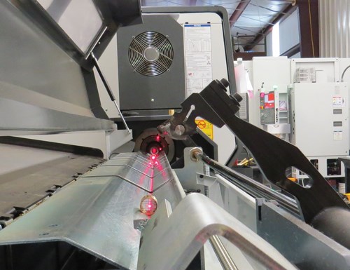
The L56SS bar feeder alignment system from Laser Tools Company Inc. was designed as an affordable, simple system to enable shops to quickly and accurately check bar feeder alignment. The system uses a straight beam of laser light and two targets to center and position the bar feeder carriage to the right height for supplying barstock material to the lathe spindle. The alignment of the center of the bar to the center of the spindle is critical because the barstock is automatically pushed or fed into the lathe’s spindle in order to begin the machining process. Proper alignment reduces wear on spindle liners and guide bushings, ensures correct remnant release, assists in end of bar management, and saves valuable setup time.
Each bar feeder alignment system includes the AP15 Aperture Pack with 1/16 inch, 3/32 inch and 1/8 inch apertures. The apertures are used to resize the laser beam for best overall viewing preference. The small, 1/16 inch aperture is used for short distances of less than 15 feet. The large apertures are for distances as long as 30 feet. The laser can be used without an aperture for longer distances.
A recent change in the system design allows the magnetic spindle adapter to accommodate bores as small as 0.0393 inch (1 mm) for efficient operation with Swiss-type machines. On Swiss machines, the AP56 magnetics spindle adapter and laser assembly should be mounted onto the headstock over the spindle collet. One target should be placed at the entry point of the bar feeder and the other at the furthest point on the bar feeder.
How it Works
To align the bar feeder, the L56 industrial alignment laser is chucked within the lathe’s spindle so that the laser beam shoots through the spindle and down the carriage of the bar feeder. Two targets are used to register the vertical and horizontal positions of the front and back portion of the bar feeder’s carriage. The left and right of center is adjusted during the installation of the bar feeder, but is often readjusted when the feeder is moved or bumped. Depending upon the style of bar feeder, the height is adjusted manually each time a new diameter of barstock is loaded into the bar feeder.
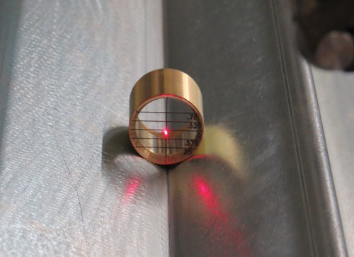
The laser beam is concentric to the case of the laser and will automatically center within the spindle when the chuck or collet is closed. A transparent target with graduations is placed onto the carriage and close to the spindle opening. A second translucent target is placed onto the carriage at the furthest point. The laser is designed to shoot through the first transparent target and onto the second red translucent target. The laser beam goes through the second target in order to focus on the exit side of the target. This is where the height graduations are located.
The alignment system is designed as a preventive maintenance tool and to assist in decreasing setup time. It can reduce maintenance costs, emergency repairs, energy consumption, vibration and unplanned downtime to contribute to optimized production.
Related Content
Tips for Troubleshooting and Repairing Chip Conveyors
A nonfunctioning chip conveyor can cause a high-production machine to be down for an extended period of time. Here is some troubleshooting advice if you’re having issues with your chip conveyors.
Read MoreReinventing the Wheel with Robot-Automated CNC Multitasking
One race team discovers how to efficiently manufacture a new wheel nut design for the next-generation NASCAR stock car with the help of a CNC mill/turn and a built-in robot.
Read MoreStarting Small with Automation
Quick-change workholding and flexible robotic automation started this small shop on the path to success.
Read MoreAutomation in the Alps: Studer AG Unveils New Grinding Concepts
Studer AG, member company of United Grinding, held its annual press conference at its Swiss Alps location earlier this month to announce its new automatic loaders to accompany its existing grinding machines as well as other offerings and automation features.
Read MoreRead Next
The Evolution of Feeding Barstock
When the ancient Egyptians employed the first known turning machines, productivity was probably not a top-of-mind issue. Given an abundance of slave labor, it’s likely the pharaohs enjoyed relatively low production costs. Today, of course, improving productivity is critical in any manufacturing operation that does not rely on plentiful, cheap labor.
Read MoreEmerging Leaders Nominations Now Open
Here’s your chance to highlight a young person in your manufacturing business who is on the path to be a future leader moving your company forward.
Read More5 Aspects of PMTS I Appreciate
The three-day edition of the 2025 Precision Machining Technology Show kicks off at the start of April. I’ll be there, and here are some reasons why.
Read More


.png;maxWidth=300;quality=90)


