Turning Toward The Future
This new machine tool represents the lastest in a new generation of CNC multi-spindle automatics. Its development was a clean sheet approach and the results are impressive.
Interpolation on the cross slide using X, Z and C axes provide the ability to mill a flat even though the tool is moving in an arc. The result is an accurate Y-axis cut.
It’s a Saturday and once again I find myself at the airport preparing to fly to Europe. My seatmate on the trip to Cologne, Germany, is Jim Trunk, president and CEO of Schütte’s U.S. operation in Jackson, Michigan.
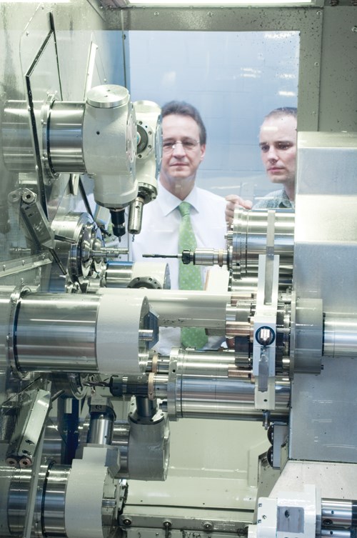
Our mission is to allow me to explore the innards of the company’s new SCX series of CNC multi-spindles. Experience has taught me this is usually best done on the factory floor.
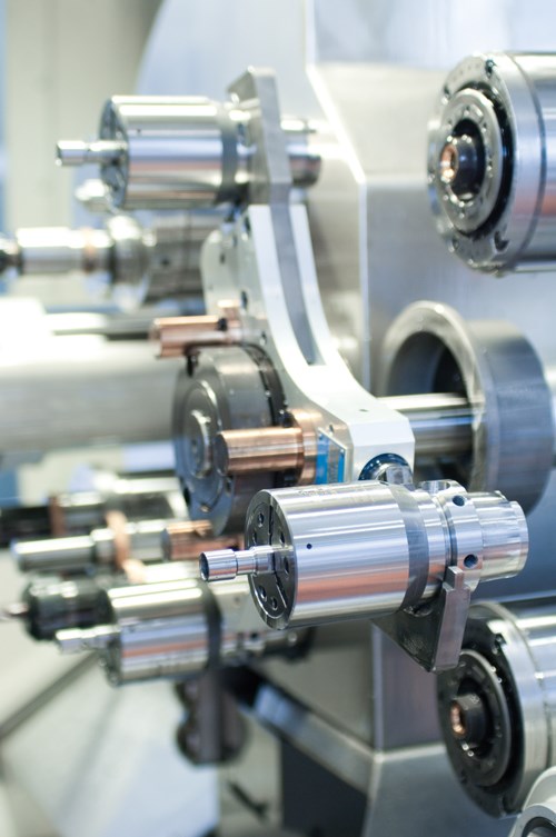
I had seen the machine twice at shows in Europe, but I found just watching it operate is insufficient to really understand how it works, in particular because the work zone is devoid of slides, motors, coolant lines, accessory drive shafts and most of the other typical actuation clues found on conventional multis. It was well worth losing a weekend to be able to get my mind around the whys, whats and hows of this new machine by seeing it in the build.
Design Intent
The first order of business for any builder designing a contemporary multi-spindle is to incorporate sufficient production flexibility to accommodate the range of parts that shops now need to run across such a machine. On the SCX this takes the form of what the company calls a “multi-single-spindle” machine that combines diverse machining capabilities of a multi-spindle with easy setup and operation of a single-spindle.
The machine is modular with all tool positions equal and all spindles equal. Tooling units mount using standard quick-change couplings. There is no operational compromise from one station to another. This enhances process optimization by allowing any tool to be used at any position. Even attachments are modular to work on any station.
Moreover, to accommodate change-over, anything not directly related to machining parts was eliminated from the working area of the machine. The enclosed cutting area contains no drive components or guideways, lubricating or coolant lines, or wiring. It’s a clean work zone that better facilitates access for quick change out of tooling, less restricted chip evacuation and freedom for adding or deleting various machining configurations.
Modularity allows the SCX to be offered in three levels of sophistication. The SC6-26 is a straight stick 26-mm six-spindle machine with no opposed spindle or rear machining capability for simple parts. Model SC7-26 uses an opposed seventh spindle as a pickoff. Cross slide tooling from station six provides limited backworking capability on this model. But it’s the SC9-26 that provides backworking capability from two additional spindles and two full function machining stations.
At Its Heart
Overall accuracy of any multi-spindle starts with construction and alignment of the spindle drum. The six-spindle carrier on the SCX uses a three-part Hirth coupling and locking mechanism that precisely establishes repeatable positioning at each station.
Each spindle uses an independent, liquid cooled motor with programmable speeds from zero to 7,000 rpm on the 26-mm model. With each spindle independently driven, C-axis and spindle stop can be programmed at all stations.
Schütte uses a decentralized controller to drive the integral spindle motors. It has no moving cabling to the spindle motors. Electric connections are maintained using a slip ring that allows the spindle drum to index continuously.
Decentralizing the control unit keeps it clear of heat and contamination. Using the slip ring also allows for programmed spindle speed adjustments “on the fly” as the drum indexes. This increases cycle time by integrating spindle acceleration, deceleration or stop concurrent with the drum index.
Compound Cross Slides
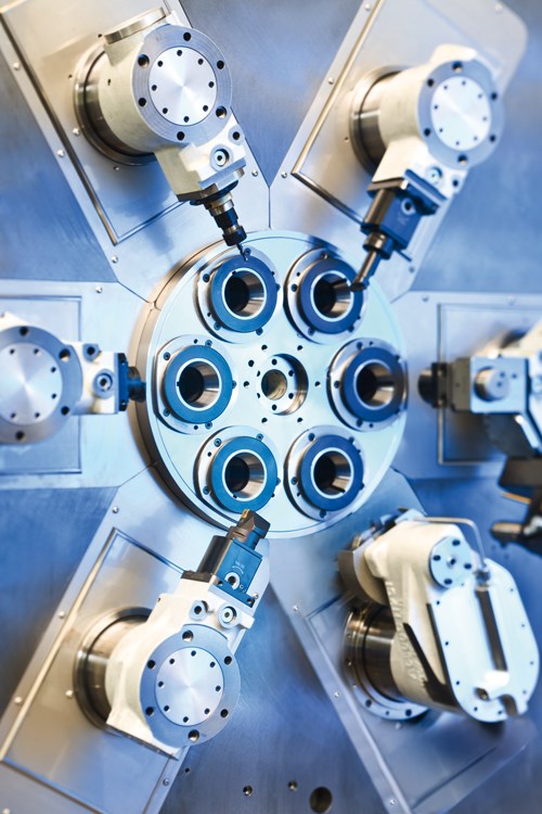
Oriented at 60-degree intervals around the spindle drum, the compound cross slides are identical for each spindle position. The X-axis slide moves radially to the spindle centerline on linear guideways. Z-axis motion uses a hydrostatic quill design that travels parallel to the spindle centerline and passes through the X-axis carrier at 90 degrees. Both axes are driven electromechanically. Using interpolation, these deliver X-Z compound motion at all six stations.
Only the Z-axis quill travels in the machining zone. On its face, a Hirth coupling is used to accept variously configured turrets that carry cutting tools used for a given station.
The standard connection allows any tool turret to be positioned on any cross slide. This modular design is suitable for both stationary and live tooling. For driven tools, an integral motor is mounted in the Z-axis quill and generates 10,000 rpm.
Coolant lines are also routed through the quill, keeping the work zone uncluttered. Through the tool coolant up to 100 bar is available.
These modular cross slide tool turrets can bring one, two or three tools into the cut at any of the six stations, potentially tripling the number of cutters that can be used at any given station. This flexibility allows for multiple operations to be performed at a single station or gives the option of having redundant tools in place for untended operation.
The cross slide turrets also use HSK or Capto cutting toolholders for solid clamping and quick change-over. Standard and accurate cutting tool interfaces encourage the use of offline tool presetters to further expedite tool changes in the machine.
And it gets better. Each cross slide can provide Y-axis machining capability as well. It’s a move made possible by the configuration of the SCX cross slide design.
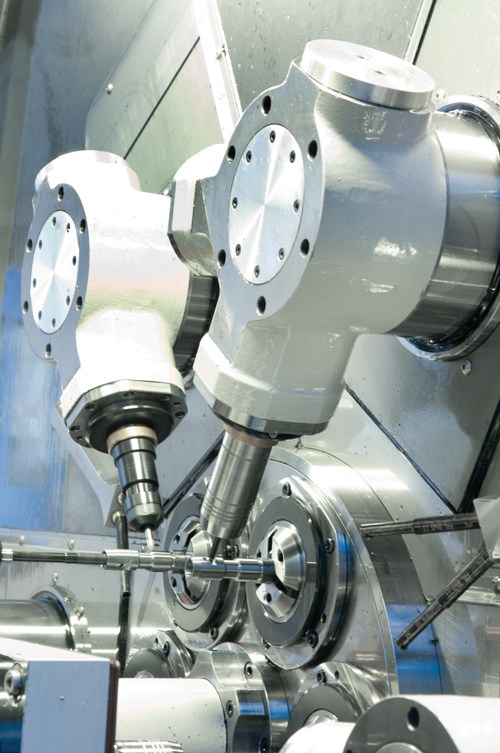
In addition to its linear motion, the Z axis can be arranged to swivel. This motion allows a second or third tool to be positioned on the workpiece. It also allows for Y-axis milling when interpolated with the linear X axis and the rotary C axis on the spindle.
The combination move allows the arc of the swiveling Z axis being fed by the X axis while the swivel motion is offset by the C axis, keeping the cutting tool normal to the workpiece surface. The result is accurate execution of a Y-axis cut, such as milling a flat. It is an operation made possible by the application of programmable servomotor technology. This can be done on any of the six stations. (Click on the first video)
Capable Endworking
The modular concept used on the cross slide units carries over to the endworking units. Machining of the workpiece face is carried out by endworking tools mounted on round pushers that are supported by hydrostatic bearings. Cross slide turrets also can be fed in the endworking direction.
When the endworking pusher is fed longitudinally, cutting forces act linearly on the rigid quill, thereby avoiding bending moments on the toolholders. These quills can carry as many as two live or stationary cutting tools. Like the cross slide units, drive motors for live tools are mounted in the endworking quill.
Using the two-tool turret allows sequential operation, such as drilling and tapping, to be carried out at one station. Or, it can provide a redundant tool position for longer uninterrupted part runs.
The Z-axis quill can be rotated providing Y-axis machining for slide milling or eccentric drilling operations. It, in effect, becomes a Y/Z compound slide for these operations.
A standard interface on the quill allows use of numerous attachments such as wobble broaches, thread whirling and polygon turning. The location of these attachments or any tooling scheme is unrestricted to any specific endworking position.
Life After Part-Off
The design of the SCX opens up a new dimension in machining the part-off side of the workpiece. Often, backworking calls the cycle time tune on a multi-spindle machine, in part because most multi-spindle machines lack sufficient tools or stations to synchronize front and backwork, especially on complex parts.
Schütte addresses this traditional multi-spindle weakness on the SC9-26 by transferring the workpiece to another machining area where the second side is machined in two more stations, eight and nine.
Each spindle is serviced by a fully articulated machining unit, like the cross slide unit. As many as six additional stationary or live tools can be brought to bear on the workpiece, finishing the part in two cycles.
Transfer to the two additional machining stations takes place after the part is cut-off in station six. The opposed spindle (number seven) works as the pickoff and holds the part in a collet or three-jaw chuck during the rest of the second side machining process.
The collet or three-jaw chuck features an HSK quick-change interface. HSK ensures positioning repeatability as the part moves from station to station. An automatic blow-off ensures the HSK holder seats properly in the machine spindles.
It’s a ballet of synchronous motion. From spindle seven, a three-station manipulator moves the clamped workpiece to station eight and simultaneously transfers the part in station eight to station nine and transfers the finished part from station nine back to station seven, where it is picked from the collet or chuck and deposited on an outgoing conveyor. (Click on the second video)
All these moves take place at the same time. Since both backworking spindles are in the cut, one cycle effectively doubles the backworking time available. In other words, if the cycle time for frontworking is 8 seconds, 16 seconds or two cycles are available for backworking operations.
The machining units, toolholders, attachments and tooling systems used for the rear side machining operations correspond to those used on the frontworking stations. The same flexibility available for processing parts in the machine’s headstock can be used on the back side, including Y axis, live drilling, milling and polygon turning. No longer is it necessary for second side operations to determine part processing sequence.
Integral Workhandling
Relying on gravity to handle parts is becoming less acceptable by many shops. This is especially true for complex, high-value-add workpieces where appearance is often a specification.
On the SC9-26, an integral workhandling system is available to satisfy this need. As mentioned, the finished workpiece is placed on an outbound conveyor.
The conveyor takes the part from the work zone and operates concurrent with cycle times less than 5 seconds. Finished parts are then placed in a pallet. The pallet station is accessed from outside the working zone so production is uninterrupted when changing pallets. All of the workhandling axes use numerical control for quick and easy change-over from job to job.
Under Control
If the spindle drum is the heart of the multi-spindle, then the CNC is its brain. The SCX uses the Siemens 840D to keep everything running. Its channel composition enhances the idea of “multi-single-spindle” automatic.
To help programmers of these machines, Schütte developed software specific to the machine, including optimization routines for multi-spindle machining, tool offset management and canned cycles for frequently used routines. Sensing in the form of tool force monitoring is available as well as DNC.
Related Content
Shop Sets its Sights on Precise Tool Alignment
A Wisconsin shop has found that visual tool alignment technology has improved tool life and surface finishes for its Swiss-type lathes while increasing throughput as well.
Read MoreCAM-Driven Lathe Questions
There can be hidden issues using legacy cam-driven lathes that can be overcome using new CNC technology. Here are three to keep in mind.
Read MoreShop Optimizes its Swiss-Turning Flexibility
Paramount Machine uses various Swiss-type lathes, some with a B axis, to produce parts more effectively than it did on conventional chucker lathes. Today, nearly every job under 1.5 inches in diameter runs across those machines even if the batch size is a mere 5 pieces.
Read MoreGetting More Production From Swiss Turning Centers
Buying a new CNC Swiss turning center is a substantial investment. For the best return, look closely for capabilities that enable the best utilization of the machine.
Read MoreRead Next
Meet The Multi-Center
How shops use the multi-spindle machine tool is changing. Complex workpieces, shorter production runs, rapid change-over and single part handling reflect the new reality of multi-spindle production. Builders are responding to these changing needs with new ways to make the multi-spindle machine more profitable, useful and efficient.
Read MoreRethinking The Multi-Spindle
When the Index MS line, with its open front-end design, hit the streets 4 years ago, it was obviously different. The question is why is it so different? The answer is revealing.
Read MoreSeeing A Multi Through Different Eyes
Sometimes if you don’t 'know' any better, applying technology in new ways simply makes sense. That’s partly what helped drive this family-owned OEM to acquire its first, and so far only, multi-spindle to help it get a better handle on production and inventory control.
Read More




.jpg;maxWidth=150;quality=70)


.jpg;maxWidth=300;quality=90)





.jpg;maxWidth=400;quality=70)
