Volumetric Measurement For Practical Positioning Accuracy
Using a conventional laser interferometer to measure the straightness and squareness errors can be difficult and costly. The process can require days of machine downtime, even with an experienced operator performing the measurements. To address the need for faster, more accurate machine calibration, Optodyne, Inc. (Compton, California) has developed a laser vector measurement technique for the 3D volumetric positioning error measurement.
The quality standards that must be maintained to stay competitive in the global marketplace force shops to continually find ways to get tighter tolerances and higher feed rates from their machine tools. To achieve these goals and to produce high-quality, accurate parts, the positioning accuracy of the machine tool becomes more and more critical.
Twenty years ago, the largest machine tool positioning errors were leadscrew pitch error and thermal expansion error. As those issues have been reduced over time through better ballscrews or linear encoder and pitch error compensation, squareness and straightness errors have become areas of greater concern. To achieve higher 3D volumetric positioning accuracy, all three displacement errors, six straightness errors and three squareness errors should be measured and compensated. Even in turning applications, requirements for positioning accuracy are becoming increasingly critical.
Using a conventional laser interferometer to measure the straightness and squareness errors can be difficult and costly. The process can require days of machine downtime, even with an experienced operator performing the measurements.
To address the need for faster, more accurate machine calibration, Optodyne Inc. (Compton, California) has developed a laser vector measurement technique for the 3D volumetric positioning error measurement. The measurement can be performed in a few hours instead of the days it could take a conventional laser interferometer. This technique brings 3D volumetric calibration to a more practical level so that shops can achieve higher accuracy and tighter tolerances while maintaining the productivity standards required to remain competitive.
In place of conventional one-dimensional linear laser calibration equipment, Optodyne’s 3D volumetric positioning error calibration system, with Laser Doppler Displacement Meter (LDDM) equipment, enables a shop to take precision measurements and detect problems before critical production runs. The system is designed to provide more complete data with fewer measurements in considerably less time. Unlike measurement with a conventional laser interferometer, this system measures vector errors including vertical and horizontal straightness, rather than only displacement.
In 3D horizontal and vertical milling operations, the volumetric error measurement method used by Optodyne’s system takes advantage of sequential-step diagonal measurements to collect 12 sets of data with four body-diagonal setups. Based on this measurement data, all three displacement errors, six straightness errors, and three squareness errors can be determined. The measured positioning errors can be used to generate a 3D volumetric compensation table that is uploaded into the controller for correcting any positioning errors and improving positioning accuracy. The system also provides an advantage in turning operations, although not to the same extent as in milling. The 2D (X and Y axes) turning operations require only two measurements to obtain four sets of data, versus the 12 data sets for X, Y and Z in milling.
Because body-diagonal displacement measurement is sensitive to linear displacement error, straightness error, angular error and thermal-induced error, standards such as ASME B5.54 and ISO 230-6 recommend measurement of the body-diagonal displacement errors for a fast check of volumetric performance. The process can be validated as an alternative to such traditional instruments used in assembly as the optical collimator, straightedges and the granite square.
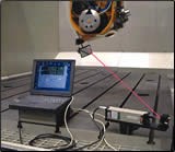
Optodyne’s LDDM technology employs a single-beam, modulated laser reflected off a movable target. The beam is detected and processed for displacement information, which is used to create the lookup table that enables the controller to compensate for errors. Setups are quick because, unlike a conventional laser interferometer, this system does not require an offset for a return beam. The only two components that need to be aligned are the laser head (with a single aperture for emitting and receiving the beam) and a flat mirror that acts as a target.
The laser and the flat mirror are mounted on the table and in the spindle. Then, instead of all three axes moving simultaneously along the body diagonal for data collection at each preset increment, the laser moves along each axis separately and in sequence. The sequence alternates along the X axis, Y axis and Z axis, and is repeated until the opposite corner of the diagonal is reached. The laser beam direction of measurement is not parallel to the displacement direction. The diagonal positioning error is collected after each separate movement of all three axes. This technique collects three times the amount of data and allows the displacement error for each separate axis movement to be measured.
The trajectory of the target is not a straight line and the lateral movement is quite large. A conventional interferometer does not tolerate lateral movements this large and cannot take these measurements. However, the LDDM-based laser system uses a flat mirror target, so the laser beam is not displaced when moving parallel to the mirror, and the distance from the source does not change. As a result, the measurements are not affected. Automatic compensation is also provided for such environmental factors as air temperature, barometric pressure and machine temperature to compensate for thermal growth.
As shops continue to look for ways to improve part quality to gain advantage in worldwide competition, they should look for strategies to produce higher positioning accuracy, tighter tolerances and higher feed rates. One method that might assist in taking these steps is volumetric calibration and compensation of machine tools.
Related Content
Does a Scanning Probe Make Sense on a Swiss-Type?
Swiss-types have limited tooling capacity, but there can be advantages to giving up some of that capacity to take advantage of a touch probe — in fact, a scanning probe — to enable in-process part measurements.
Read MoreShop Finds Value in Simple CMM Programming
Icon-driven programming enables all shopfloor personnel to perform CMM inspection, not just those in the quality department.
Read MorePMTS 2023 Product Preview: Measurement
Learn about some of the latest measurement solutions that will be on display at PMTS 2023.
Read MoreAutomated Inspection Transforms Medical Manufacturer’s Quality Control
Manual steps for part inspection have been eliminated with a new CMM process using more advanced software and strategies such as using a combined scanning/touch-trigger probe.
Read MoreRead Next
Process-Oriented Measuring Technology For Turning Tools
Because tools create the geometric shape of a workpiece, the accuracy of this shape is dependent on the position of the cutting edge to the workpiece. Therefore, the position of the cutting edge should be identified and maintained as precisely as possible. One reliable method for achieving the accuracy needed is through the use of a laser system for tool setting.
Read MoreDo You Have Single Points of Failure?
Plans need to be in place before a catastrophic event occurs.
Read MoreSeeing Automated Workpiece Measurement in Real Time
User-friendly inspection software for CNC machining centers was shown at IMTS 2024 monitoring measurements between and after machining while performing SPC based on recorded measurement values.
Read More


.jpg;maxWidth=300;quality=90)


