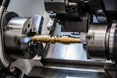
Working with customers to reduce machining difficulty can result in part designs that can be manufactured faster and less costly.
Design for manufacturability (DFM) is not new. Still, a healthy number of product design engineers are not applying DFM. It’s possible that new designers, especially those whose companies outsource most or all of their production work, simply haven’t rubbed elbows with manufacturing types very often. As a result, they are less likely to have a handle on what modern manufacturing processes can and, more importantly, cannot do. On the other hand, product development cycles have become so compressed there may not be sufficient time to consider DFM, let alone fully embrace the valuable design discipline.
Regardless, no doubt you will continue to be asked to magically create components from time to time that are (1) impossible to machine or (2) impossible to machine at a reasonable cost. Slight design changes would make machining much cheaper in some cases. However, if you’re presented with a component near the end of the product development cycle that would be nasty to machine, it may be too late to integrate your helpful design tweaks.
The key here is establishing an effective line of communication between your shop and your customers — more specifically, the customers’ design engineers — early on in the new product development process.
To get more insight about this, I had conversations and email exchanges with Emma Lambert. Lambert is the vice president of Formed By Design, a company that offers collaborative design and analysis consulting services. She also has a master’s degree in mechanical engineering from the University of Southern California and worked at the NASA Jet Propulsion Laboratory for more than three years where she performed engineering design and structural analysis for the Mars 2020 and Mars Sample Return missions.
Lambert cites the importance of working toward the development of a common language that can be used to symbiotically transfer or exchange information between designers and manufacturers, a process that can continually be improved and fine-tuned. Lambert also notes there are nontraditional ways in which shops can open and foster effective and integrated lines of communication with their customers in order to facilitate the growth of mutually beneficial relationships.
What follows is an edited version of a note she sent to me describing how machine shops can use engineers and analysis methods, such as finite element analysis (FEA), as the tools/means of developing these communication lines and relationships.
Improving Communication in the Words of Emma Lambert
One might wonder what is the current problem with communication in the free market between machine shops and engineering companies. There are many answers to this question, but one relates primarily to different structures and types of organizations. Large organizations (think NASA, Boeing, Lockeed Martin and so on) are typically structured in ways that enable fairly fluid internal communication and, as a result, more optimized design iteration (particularly as DFM has grown). At such organizations, there exists, within the context of a larger “whole,” smaller sections, divisions and groups — manufacturing, analysis, quality and design, for example — each of which have a different focus and specialty as well as strengths and weaknesses.
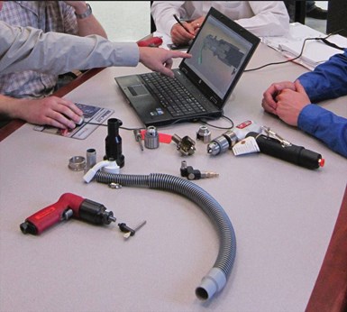
Input from all manufacturing departments should be solicited when considering how best to streamline production while optimizing new product designs.
Inherent in this kind of organizational structure, where the “whole” is divided into “parts,” integration between the parts and the whole is much more direct and coherent because there exists a common language known to the organization. That is, communication and relationships between those in engineering and manufacturing originates and evolves organically. While there are also inherent limits to this kind of structure, this top-down approach can have its advantages when it comes to the form and ease of communication between different information channels. The transfer of information occurs much more easily.
Now, consider a collection of independent organizations that exist in free space. In the nonbureaucratic realm, there is an inherent bottom-up organizational structure — unlike what’s mentioned above in which individual parts exist independently, yet work together with other individual parts to create an integrated whole. The whole and the parts exist in both cases, but the ways in which they are sewn together differ.
Examples of this bottom-up structure could be machine shops providing manufacturing services to engineering consultancies or engineering consultancies, providing design and analysis services for a product. Each entity functions as a customer and vendor in various capacities for each other in order to develop the whole. In this sense, all of the components are still there, but they need some sort of “glue” to come together.
This glue will be different depending on how each organization chooses to communicate and build relationships with each other. In other words, there might be multiple languages that must be learned and integrated as opposed to a single common language. There are many different ways this language can be developed. However, it is generally mutually beneficial to determine ways that enable a greater ability for each to understand each other and reach common ground. This could relate to faster turnaround time, reduced cost and increased knowledge. So, the goal is to get each entity to learn the other’s language.
Some shops might believe they do not have the power or capacity to provide input into designs they are given or do not know how to communicate such information, even if those changes would benefit both parties. Likewise, sometimes engineers do not know, for example, that certain features of parts are simpler or more complex to manufacture than others and that certain design changes could potentially drastically affect the time and cost to manufacture the part. In the case of machine shops, developing a communication stream that bridges this gap and offering a language that can be understand by all involved enables knowledge transfer that ultimately benefits both parties in the long run.
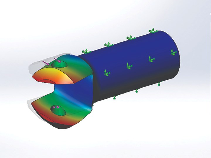
The original design for this component used a rectangular shaft. Contract shop Parametric USA’s first DFM iteration changed it to include a cylindrical shaft with bull-nose yoke, reducing manufacturing costs by 75%. (Photo Credit: Parametric USA)
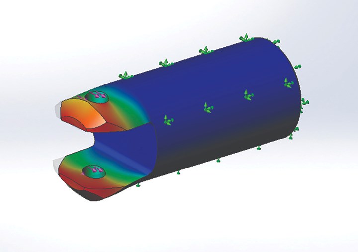
FEA showed deflection due to side loading was too much, however, so Parametric USA performed another DFM iteration. By increasing the shaft diameter to remove the bull-nose feature, turning and grinding was made simpler and faster, and an off-the-shelf slide bearing could be used. The estimated savings for 1,000 parts is approximately $33,000. (Photo Credit: Parametric USA)
So, the question then becomes: how does one do such a thing? Specifically, how can machine shops streamline communication with design engineers to build better relationships with their customers? What are the common entities? Where is the common ground? How do they learn from each other?
This question can be answered in many ways, but let’s focus on two in particular. The first is opening a line of communication early in the process of customer development and offering engineering support as a means to bridge the gap. It can be beneficial to learn from business structures such as startups, where developing relationships with customers and stakeholders is key to success.
A key aspect often seen in startups and small businesses are the structure and intention behind the initial business development kickoff meetings, where the shop’s team might go to the potential customer and discuss project goals, requirements, potential concerns, what design aspects can and cannot be changed or modified, and potential ideas or plans of action. What this initial meeting does best, however, is that it opens a communication stream with the customer early on in the relationship-building process so these concerns and potential learning opportunities are brought up while there remains the ability to easily adapt.
As opposed to shops being passive players in providing an end product, they should strive to become active participants in the product development process, providing yet another means to provide quality service to their customers and putting them first. This shows interest in ensuring the customer gets quality parts in reasonable amounts of time, while also making their job potentially less time- or money-consuming. This information can also enable engineers to design parts more optimally for manufacturing as manufacturing concerns are raised in such a way that the downstream work is carried out more efficiently as well. If a shop was to provide additional input into what may or may not be optimal for manufacturing time or cost, it is both helping itself and its customers.
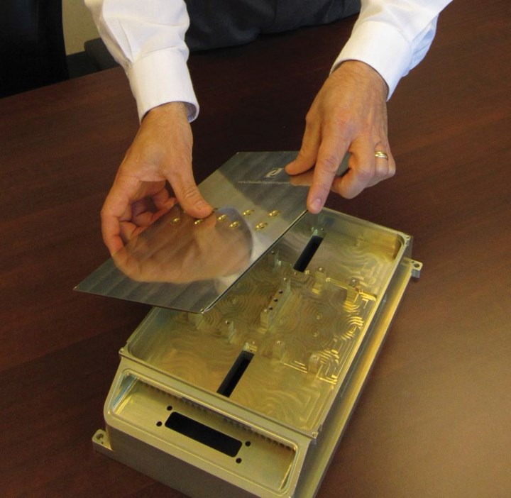
Domaille Engineering, a contract manufacturer in Rochester, Minnesota, calls its DFM approach “Engineering to Manufacturing” (E2M). The company first strives to get a clear understanding from the customer about the product’s purpose, how it’s assembled and how it functions. This provides the firm footing necessary to effectively apply DFM, which can lead to sensible changes in part materials, geometries, tolerances or manufacturing processes. In fact, a DFM project for an electronics housing led Domaille Engineering to develop its “no-bolt” concept that enables housing covers to snap firmly into place without requiring fasteners, as shown here.
The second is establishing the optimal means of communicating such information while determining how engineering tools and processes can be utilized to gain the trust of customers and transfer the information in ways their customers’ engineers can understand.
Machinists tend to work intuitively, while engineers work quantitatively. Engineers would like to know how changes in the design of a part will affect its failure modes, stress distribution and overall product performance. The engineers know how the part must behave on their end in its functional environment and the machinists know how the part must be manufactured to meet performance requirements. So, how do both parties learn from each other regarding this?
The engineers can provide insight into what does and doesn’t matter for a given new design and shops can show how proposed changes affect the part. Within the design process, FEA is often used to better understand the mechanical behavior of parts. FEA discretizes a physical object into computational “elements” that are used to calculate the displacements and forces in each discretized region and, as a result, the stress and strain in the part, indicating whether or not the part will survive its load environment.
To facilitate this communication process, shops might consider bringing engineers, particularly those with FEA experience, to speak to customers and perform analysis on proposed changes to parts. FEA can be used as a tool to provide confidence to customers through quantifiable data showing that proposed changes to the design to optimize for manufacturing do not affect the part in ways detrimental to its functional performance or structural survival. It can also be a learning opportunity for machinists to understand why certain design changes are implemented.
Related Content
CAM Software’s Place Serving Emerging Trends
SolidCAM aims to align its product development and customer engagement strategies to address the evolving needs and challenges of the manufacturing industry.
Read MoreMastercam 2024 Integrates Sandvik Coromant CoroPlus Tool Library
The integrated library enables users to work faster when importing tool geometries and cutting data.
Read MoreLone Shop Machinist Benefits From Five-Axis CAM Modules
This California shop owner applies five-axis strategies for more efficient milling of parts with challenging geometries, free-form surfaces and deep cavities.
Read MorePrecision Machining Technology Review: August 2024
Production Machining’s August 2024 technology showcase includes some of the latest technology from SW North America, Tsugami, Siemens, Select Manufacturing Technologies, Hurco and ECI Software Solutions — all on display at IMTS 2024.
Read MoreRead Next
Shop Optimizes its Swiss-Turning Flexibility
Paramount Machine uses various Swiss-type lathes, some with a B axis, to produce parts more effectively than it did on conventional chucker lathes. Today, nearly every job under 1.5 inches in diameter runs across those machines even if the batch size is a mere 5 pieces.
Read MoreGrowth Comes When Machining Challenges Are Met
Manufacturers such as SDP/SI that embrace machining challenges ultimately find ways to become more efficient and profitable operations.
Read MoreVertical Integration Enables Rapid Manufacturing Response
For this contract manufacturer, having myriad machining and manufacturing capabilities in-house enables it to deliver assemblies to customers faster and with higher quality.
Read More



.jpg;maxWidth=300;quality=90)


